Touch Sensing Device

a touch sensing device and touch technology, applied in the field of touch system, can solve the problems of unsatisfactory linearity, control circuit is incapable of recognizing the difference between the two touch areas, and the circuit of the touch sensing device generated for these two touch areas fails to provide effective information for distinguishing different touch points, etc., to reduce the rate of misjudging a user's intention, improve the recognition capability of the control circuit, and optimize linearity

Inactive Publication Date: 2015-12-24
MSTAR SEMICON INC
View PDF13 Cites 19 Cited by
  • Summary
  • Abstract
  • Description
  • Claims
  • Application Information

AI Technical Summary

Benefits of technology

[0011]The invention is directed to an electrode pattern / electrode configuration of a mutual capacitive touch sensing device. By adopting an electrode pattern / electrode configuration different from the prior art, the touch sensing device of the present invention is capable of increasing the recognition capability of a control circuit for different touch points in the Y-direction without increasing the number of driving electrodes / driving circuits, thereby optimizing linearity and further reducing the rate of misjudging a user intention for an electronic device.

Problems solved by technology

In other words, the control circuit is incapable of recognizing the difference between the two touch areas.
If the touch areas T1 and T2 belongs to different touch points, it is apparent that the coordinate calculation results that the control circuit of the touch sensing device generates for these two touch areas fails to provide effective information for distinguishing different touch points.
However, owing to the above failure of distinguishing touch areas within the same range R, the corresponding relationship of the actual Y-coordinate and the calculation result is substantially a step-like curve C2, which apparently has unsatisfactory linearity.
Such approach inevitably causes increased hardware costs.
Such insufficient sensing amount may cause the electronic device to misjudge a real touch intention of the user or cause the electronic device to miss the user touch.

Method used


Image

  • Touch Sensing Device
  • Touch Sensing Device
  • Touch Sensing Device

Examples


Embodiment Construction

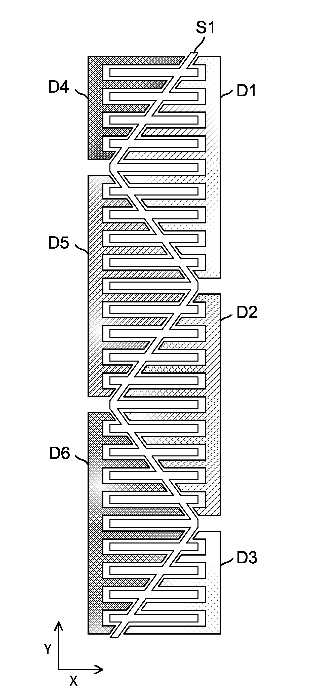
[0026]A touch sensing device is provided according to an embodiment of the present invention. FIG. 2(A) shows a partial diagram of an electrode configuration of the touch sensing device. It should be noted that, the shape, size, ratio and number of electrodes in FIG. 2(A) are merely examples for illustration purposes, and are not to be construed as limitations of the present invention. Electrodes denoted D1 to D6 are driving electrodes disposed at two sides of a sensing electrode S1. At two sides of a main body of the sensing electrode S1 are multiple recessed portions that correspond and interleave with electrode fingers of the driving electrodes D1 to D6, hence forming six different mutual capacitive sensing regions.

[0027]The driving electrode D1 is again depicted in FIG. 2(B). The driving electrode D1 includes an electrode main stem D1A and ten electrode fingers D1B to D1K. The electrode main stem D1A has a planar contour of substantially a long strip, and has its longer side sub...


PUM


Abstract

A touch sensing device includes a driving electrode and a sensing electrode. The driving electrode includes an electrode main stem and a plurality of electrode fingers. The electrode main stem has a planar contour of substantially a long strip, and has a longer side parallel to a first direction. The electrode fingers extend from the electrode main stem towards a second direction substantially perpendicular to the first direction. At least two electrode fingers of the electrode fingers have different lengths in the second direction. The sensing electrode includes a main body. The main body has a plurality of recessed portions that correspond and interleave with the electrode fingers to form a mutual capacitive touch region.

Description

[0001]This application claims the benefit of Taiwan application Serial No. 103121152, filed Jun. 19, 2014, the subject matter of which is incorporated herein by reference.BACKGROUND OF THE INVENTION[0002]1. Field of the Invention[0003]The invention relates in general to a touch system, and more particularly, to an electrode configuration technology in a touch system.[0004]2. Description of the Related Art[0005]Operating interfaces of recent electronic products have become increasingly user-friendly and intuitive with the progressing technology. For example, through a touch screen, a user can directly interact with applications as well as input messages / texts / patterns with fingers or a stylus, thus eliminating complexities associated with other input devices such as a keyboard or buttons. In practice, a touch screen usually comprises a touch panel and a display provided at the back of the touch panel. According to a touch position on the touch panel and a currently displayed image on...

Claims


Application Information

Patent Timeline
Patent Type & Authority Applications(United States)
IPC IPC(8): G06F3/044
CPCG06F2203/04103G06F3/044G06F3/03547G06F3/0443
Inventor KUO, WEI-LUNDING, PENG-YUNHO, KAI-TING
Owner MSTAR SEMICON INC
Why Eureka
Try Eureka