Rotor, Reluctance Machine and Production Method for a Rotor

a reluctance machine and rotor technology, applied in the direction of synchronous motors, magnetic circuit rotating parts, magnetic circuit shapes/forms/construction, etc., can solve the problems of comparatively complex structure and production of a rotor of this type, and achieve the effect of optimizing the starting behavior of the rotor

Active Publication Date: 2015-12-24
KSB AG
View PDF5 Cites 29 Cited by
  • Summary
  • Abstract
  • Description
  • Claims
  • Application Information

AI Technical Summary

Benefits of technology

[0013]The separation of the rotor into an inner and outer region influences and optimizes the starting behavior of the rotor. When using the rotor in a reluctance machine it is possible to dispense with the use of a frequency converter, i.e. the rotor construction according to the invention allows asynchronous rotor starting when a three-phase current with constant...

Problems solved by technology

The structure and also the production of a ro...

Method used


Image

  • Rotor, Reluctance Machine and Production Method for a Rotor
  • Rotor, Reluctance Machine and Production Method for a Rotor
  • Rotor, Reluctance Machine and Production Method for a Rotor

Examples


Embodiment Construction

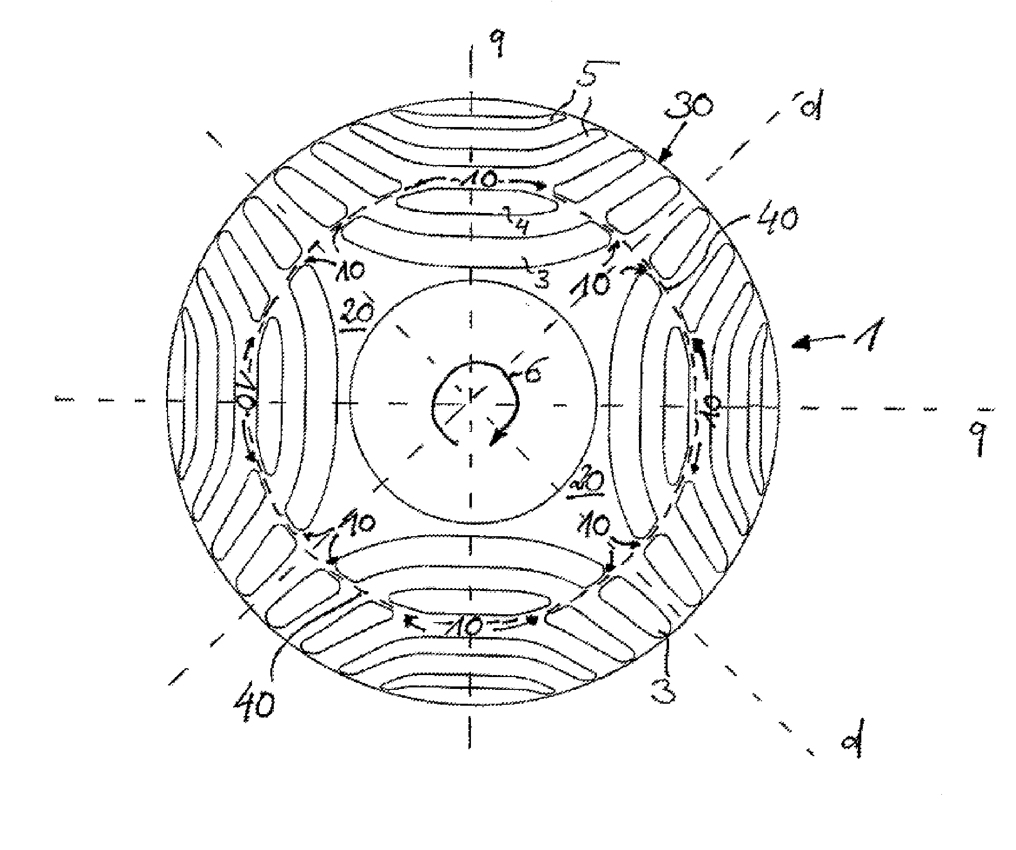
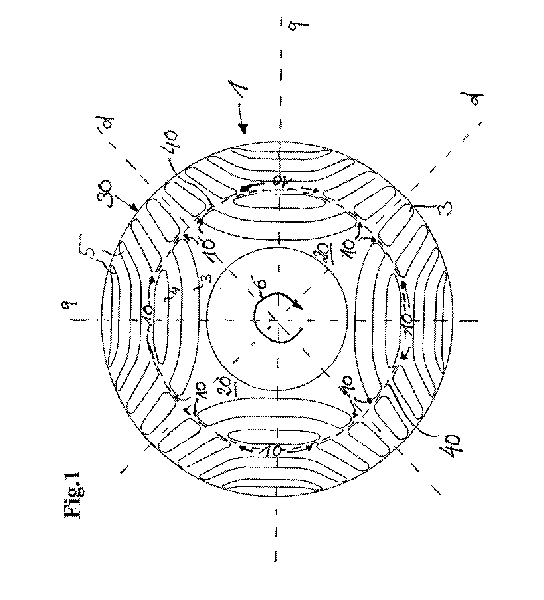
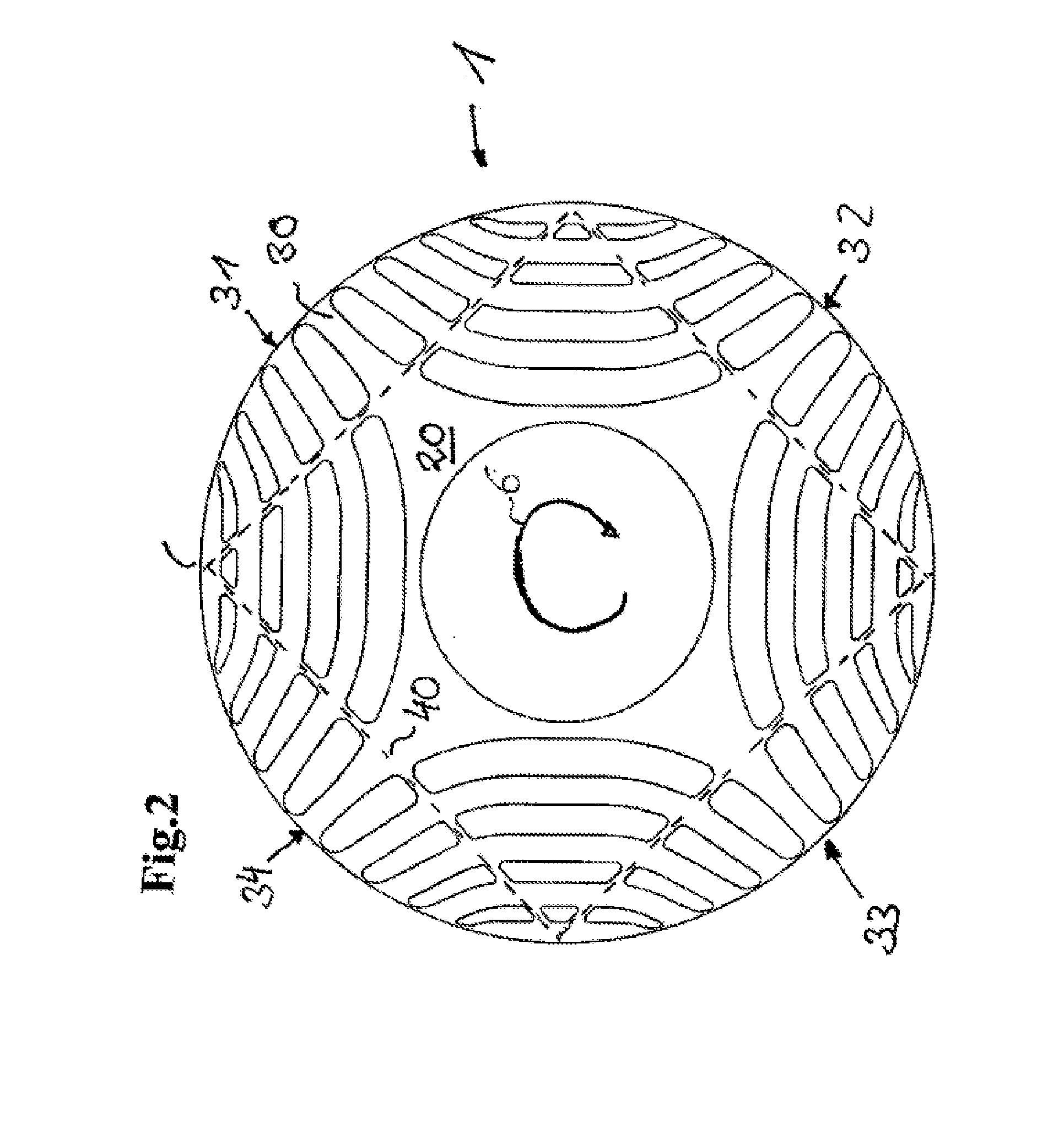
[0041]FIGS. 1 to 3 show a plan view of different rotor laminations 1, which are stacked one above the other in an axial direction, i.e. along the axis of rotation 6, for the construction of a rotor according to the invention. In order to simplify the illustration, the stator is not shown. The rotor lamination 1 has a plurality of cutouts 3, 4, 5, which take on the function of flux barriers and the arrangement of which forms a four-pole rotor, of which the magnetic flux is inhibited in the regions with the flux barriers 3, 4, 5. The region with high magnetic conductivity is generally characterized as the d-axis, and the region of low magnetic conductivity is generally characterized as the q-axis.

[0042]The assembled laminated core is mounted on a rotor shaft (not illustrated).

[0043]The arrangement of the individual flux barriers 3, 4, 5 corresponds substantially to the technical teaching of US patent specification U.S. Pat. No. 5,818,140, to which reference is made expressly in this r...


PUM

PropertyMeasurementUnit
Forceaaaaaaaaaa
Magnetismaaaaaaaaaa
Diamagnetismaaaaaaaaaa

Abstract

A rotor for a reluctance machine is provided. The rotor includes a cylindrical soft-magnetic element having cutouts for forming magnetic flux barriers. Some or all of the flux barriers are divided by one or more webs, with the profile of the individual webs forming a closed line which divides the rotor in the radial direction into an inner and an outer region. The cut-outs may be partially or fully filled with a a paramagnetic or diamagnetic filler material.

Description

CROSS REFERENCE TO RELATED APPLICATIONS[0001]This application is a continuation of PCT International Application No. PCT / EP2014 / 051901, filed Jan. 31, 2014, which claims priority under 35 U.S.C. §119 from German Patent Application No. 10 2013 201 694.8, filed Feb. 1, 2013, the entire disclosures of which are herein expressly incorporated by reference.BACKGROUND AND SUMMARY OF THE INVENTION[0002]The invention relates to a rotor for a reluctance machine comprising a cylindrical soft-magnetic element, wherein the soft-magnetic element has cutouts for forming magnetic flux barriers.[0003]Rotors for synchronous reluctance machines are usually equipped with a cylindrical soft-magnetic element, which is arranged coaxially on the rotor axis. In order to form at least one pole pair or gap pair, the soft-magnetic element comprises flux-conducting and flux-blocking portions, which differ from one another by a magnetic permeability of differing degree. The portion with high magnetic conductivit...

Claims


Application Information

Patent Timeline
IPC IPC(8): H02K19/14H02K15/12H02K1/24
CPCH02K1/246H02K19/14H02K15/12Y10T29/49014H02K15/0012
Inventor HAUSSMANN, MEIKEKANOFFSKY, FLORIANMUELLER, MARTINMUNTZ, TIMOSCHAAB, JOCHEN
Owner KSB AG
Why Eureka
Try Eureka