Sterilization container capable of providing an indication regarding whether or not surgical instruments sterilized in the container were properly sterilized

a sterilization container and container technology, applied in the direction of instruments, disinfection, lavatory sanitory, etc., can solve the problems of unfavorable processing of surgical instruments, delay in scheduling and/or other adverse disruptions, and inability to prevent microorganisms from entering the container

Active Publication Date: 2015-12-31
STRYKER CORP
View PDF1 Cites 64 Cited by
  • Summary
  • Abstract
  • Description
  • Claims
  • Application Information

AI Technical Summary

Benefits of technology

[0025]This invention is directed to a new and useful system and method for determining if surgical instruments have completed a sterilization process cycle and have met a set of required process measurements during the sterilization process cycle. The system includes a container defined by several panels. The panels define a cavity within the container and an opening into the container. The container receives surgical instruments that may be within a removable inser

Problems solved by technology

Some surgical instruments are not amenable to processing through the automated washer and are required to be manually washed.
The perforated “rigid” material provides structure to transport, handle and stack the containers of surgical instruments, but by itself does not prevent micro-organisms from entering the container.
Determining that a container of surgical equipment has not been exposed to a sterilizing agent, while preparing for a surgical procedure is disruptive to the efficiency of the operating room and requires that another set of surgical equipment be located and properly set ultimately causing schedule delays and/or other adverse disruptions.
This causes confusion for the health care workers when reading and interpreting the various chemical indicator color changes.
Unfortunately, these gases are somewhat higher in toxicity and/or are difficult to control during the sterilization process so they do not enjoy wide-spread use throughout hospital systems.
Certain reusable medical equipment such as Colonoscopes cannot be sterilized using the equipment in a hospital central processing department.
Even though these standards are accepted throughout the medical device industry by the Healthcare Regulatory agencies and the Healthcare providers, there is potential for human error, uncontrollable variability and sterilizing system equipment problems that enter into the Healthcare delivery system which may cause inconsistencies in the sterilization or disinfection results for reusable medical equipment.
Human error: the Hospital followed all instructions properly, but a heavy medical instrument that did not have a container was included inside the sterile barrier system.
Sterilization equipment problem example: a power spike advances the sterilizer by 1 minute thus shortening the actual exposure duration by that amount.
Another factor that can cause problems with the sterilization of medical devices is where a mixed load of equipment is sterilized together in a single process.
If this occurs, there could be some residual moisture retained in the equipment that requires a longer drying time.
This wicking out results in a water stain forming on the SBS wrap used on a perforated container, but the water stain is not discovered until the operating room personnel are preparing the equipment for the next surgical procedure.
The SBS materials are not designed to maintain their anti-microbial properties if they become wet.
Since it is not known when or how it became wet, the entire group of equipment becomes suspect due to the water stain and thus must be reprocessed.
The self contained biological indicators have a housing sealed to a microbial barrier material that allows a path for the sterilizing agent to penetrate and reach the biological agent, but not allow other micro-organisms to enter.
This means that at a hospital, at any given moment in time, a significant number of the hospital's surgical instruments may be in quarantine.
Requiring the hospital to maintain this large inventory of instruments can add to the cost of maintaining the hospital.
If the biological indicator test fails, all of the lots of surgical equipment

Method used


Image

  • Sterilization container capable of providing an indication regarding whether or not surgical instruments sterilized in the container were properly sterilized
  • Sterilization container capable of providing an indication regarding whether or not surgical instruments sterilized in the container were properly sterilized
  • Sterilization container capable of providing an indication regarding whether or not surgical instruments sterilized in the container were properly sterilized

Examples


first container embodiment

II. First Container Embodiment

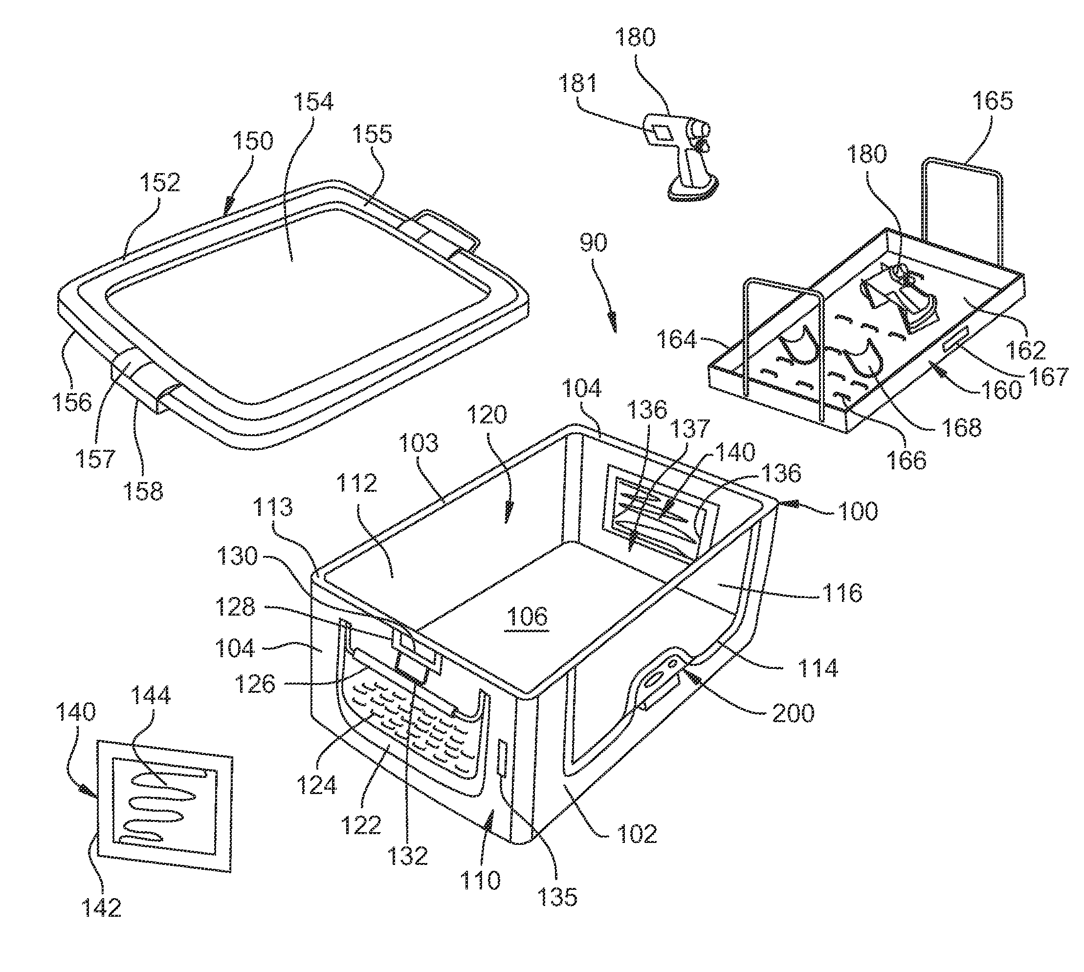
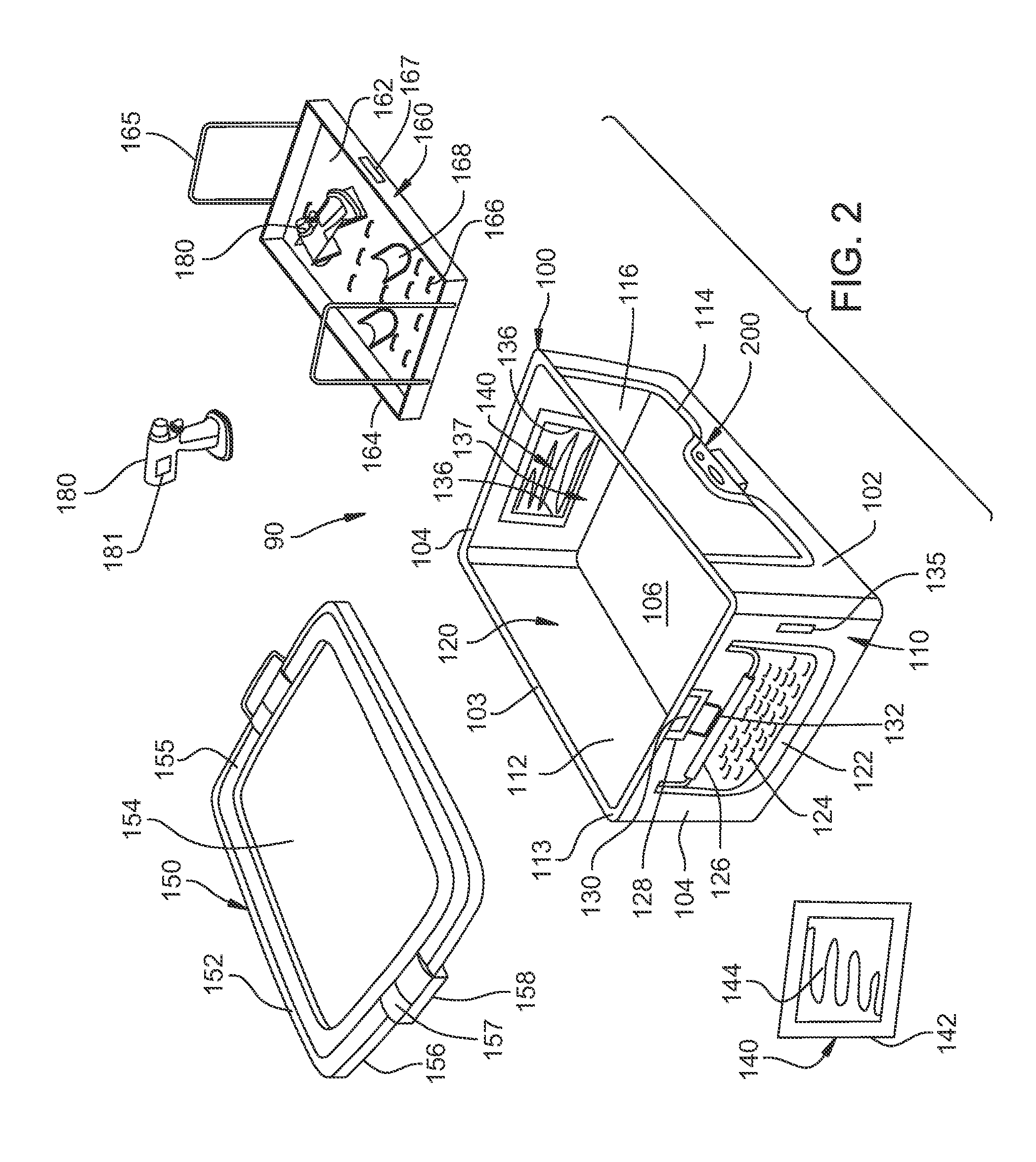
[0102]Turning to FIG. 2, a container assembly 90 of a first embodiment of this invention is illustrated. Container assembly 90 includes a container 100 that is generally rectangular in shape and is defined by an opposed spaced apart planar front panel 102, a planar rear panel 103 and a pair of opposed spaced apart planar side panels 104. Panels 102 and 103 are oriented orthogonal to panels 104. A planar bottom panel 106 is perpendicular to panels 102, 103 and 104 and forms the bottom of container 100. An interior cavity 120 is defined by panels 102, 103, 104 and 106 within container 100. Container 100 has outer surfaces 110, inner surfaces 112 and an upper peripheral rim 113. Container 100 can be formed from materials such as stamped or deep drawn aluminum, stainless steel, plastic or other suitable materials.

[0103]Front panel 102 has a window or opening 114 defined therein. Opening 114 is covered by a panel 116 formed from a material that is transparen...

second container embodiment

III. Second Container Embodiment

[0122]FIG. 5 illustrates a container assembly 300 of a second embodiment of the present invention. In FIG. 5, common reference numbers to like items in FIG. 2 have been given the same reference number. Container assembly 300 includes a container 302 that is generally rectangular in shape. Container 302 is similar to container 100; however, some features of container 100 have been omitted and other features have been added. For example, container 302 does not include any holes 124 or a filter assembly 140.

[0123]Electronic module 200 is mounted to front panel 102. Electronic sensor module 200 contains electronic components and sensors that measure environmental characteristics within container 302 and determine if required conditions have been met to insure sterility of the contents of container 302.

[0124]Container 302 further includes four rounded shoulders 304. Each of shoulders 304 is located at an interior corner 306 of container 302 and extends alo...

fifth container embodiment

VI. Fifth Container Embodiment

[0171]Referring to FIG. 9A, a container assembly 600 of a fifth embodiment of the present invention is shown. Container assembly 600 includes a version of container 402. The version of container 402 of FIG. 9A is the same as the previously described container 402 of FIG. 7A except that opening 418 is not present. Also magnets 624 are mounted to interior facing vertical side surfaces of side panels 405 and 406 slightly below rim 413.

[0172]With additional reference to FIG. 9B, cover 650 is used to cover and enclose container 402. Cover 650 includes a generally rectangular shaped panel 652. Cover 650 can be formed from materials such as stamped aluminum or other suitable materials. Cover 650 has an inner surface 651, an outer surface 654 and opposed ends 653. An array of holes 655 are defined in and extend through panel 652. Holes 655 allow sterilant to enter and leave container 402 during sterilization processing. An outer peripheral wall 656 extends down...


PUM


Abstract

A sterilization container for sterilizing at least one surgical instrument. The container includes at least one sensor for measuring an environmental characteristic of the container during the sterilization of the instrument. The measure of the environmental characteristic is supplied to a processor. The processor compares the measurement of the container environment to a validated measurement for the sterilization process. If the measured environmental characteristic is at least equal to the validated sterilization process measurement, the processor presents an indication that the surgical instruments was properly sterilized.

Description

RELATIONSHIP TO EARLIER FIELD APPLICATION[0001]This application is a continuation of PCT App. No. PCT / US2014 / 024799 filed 12 Mar. 2014. PCT App. No. PCT / US2014 / 024799 is a non-provisional application based on U.S. Prov. Pat. App. No. 61 / 779,8956 filed 13 Mar. 2013. The contents of the priority applications are incorporated herein by reference.FIELD OF THE INVENTION[0002]This invention relates generally to sterilization systems for surgical instruments. More particularly, this invention relates to a container and electronic sensor module for monitoring and verifying appropriate sterilization measurements have been met during a sterilization process and a method for using an electronic sensor module for determining if surgical instruments within the container have been properly exposed to a set of required process measurements during a sterilization process cycle.BACKGROUND OF THE INVENTION[0003]Sterilization of instruments and equipment used in medical and surgical procedures is impo...

Claims


Application Information

Patent Timeline
IPC IPC(8): A61L2/24A61L2/20A61L2/07A61L2/28
CPCA61L2/208A61L2/24A61L2/28A61L2/07A61L2202/24A61L2/26A61L2202/182A61L2202/14
Inventor BRUCE, HENNIGESCHILDERS, ROBERT W.MILLER, MICHAELMOAIERY, ALIDUDYCHA, ADAMPURRENHAGE, BENJAMIN JOHNCHEMLAR, ERIC VACLAC
Owner STRYKER CORP
Why Eureka
Try Eureka