High-intensity focused ultrasound irradiation

a high-intensity, focused ultrasound technology, applied in tomography, application, therapy, etc., can solve the problems of undesired treatment of the subject's area, further heating of the area, etc., and achieve the effect of short time, less time, and convenient operation

Inactive Publication Date: 2015-12-31
KONINKLJIJKE PHILIPS NV
View PDF13 Cites 0 Cited by
  • Summary
  • Abstract
  • Description
  • Claims
  • Application Information

AI Technical Summary

Benefits of technology

[0007]It is an object of the invention to provide improvements for high-intensity focused ultrasonic irradiation heating, which overcome at least some of the above disadvantages. In particular, it is an object of the invention to provide an ultrasonic treatment device, an ultrasonic treatment system, and a method for ultrasonic treatment, which enable treatments based on high-intensity focused ultrasonic irradiation heating, which can be easily performed, which require few time for calibration purposes, which can be performed in a short time, which can be performed with high accuracy, and which comprise a low risk of damaging areas of a subject of interest outside a target area.

Problems solved by technology

Furthermore, the effect of thermal diffusion may result in a further heating of an area, when the ultrasonic beam does not cover this area anymore.
This extends the time required for the treatment of the subject of interest and can lead to undesired treatments of areas of the subject of interest outside the target zone.

Method used


Image

  • High-intensity focused ultrasound irradiation
  • High-intensity focused ultrasound irradiation
  • High-intensity focused ultrasound irradiation

Examples


Embodiment Construction

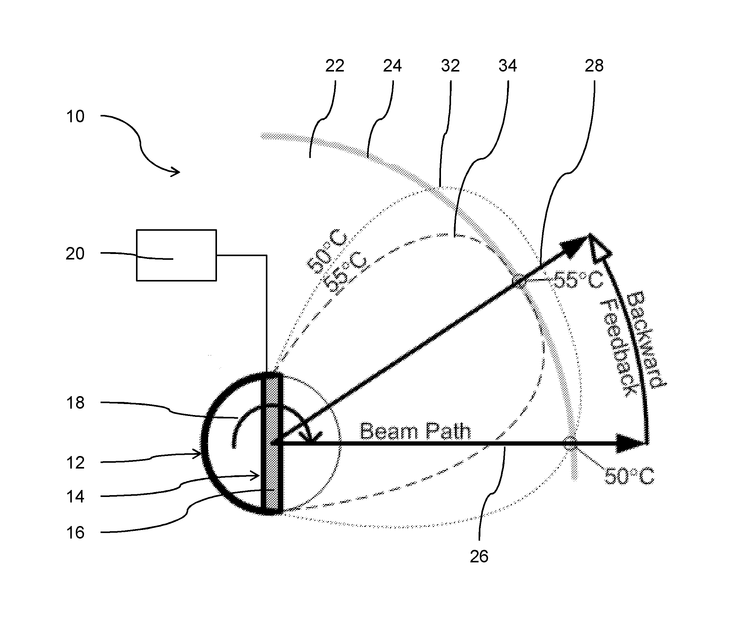
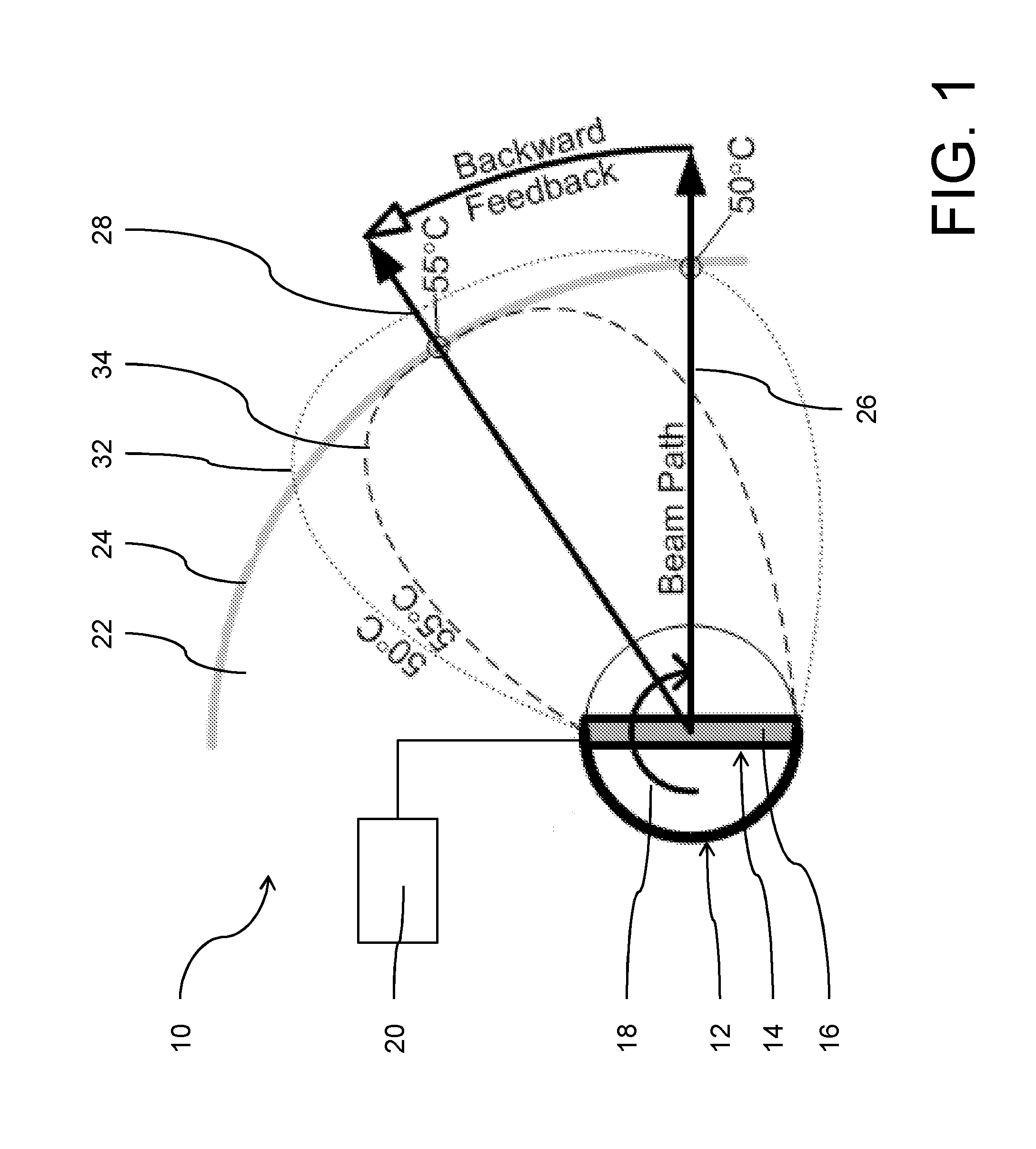
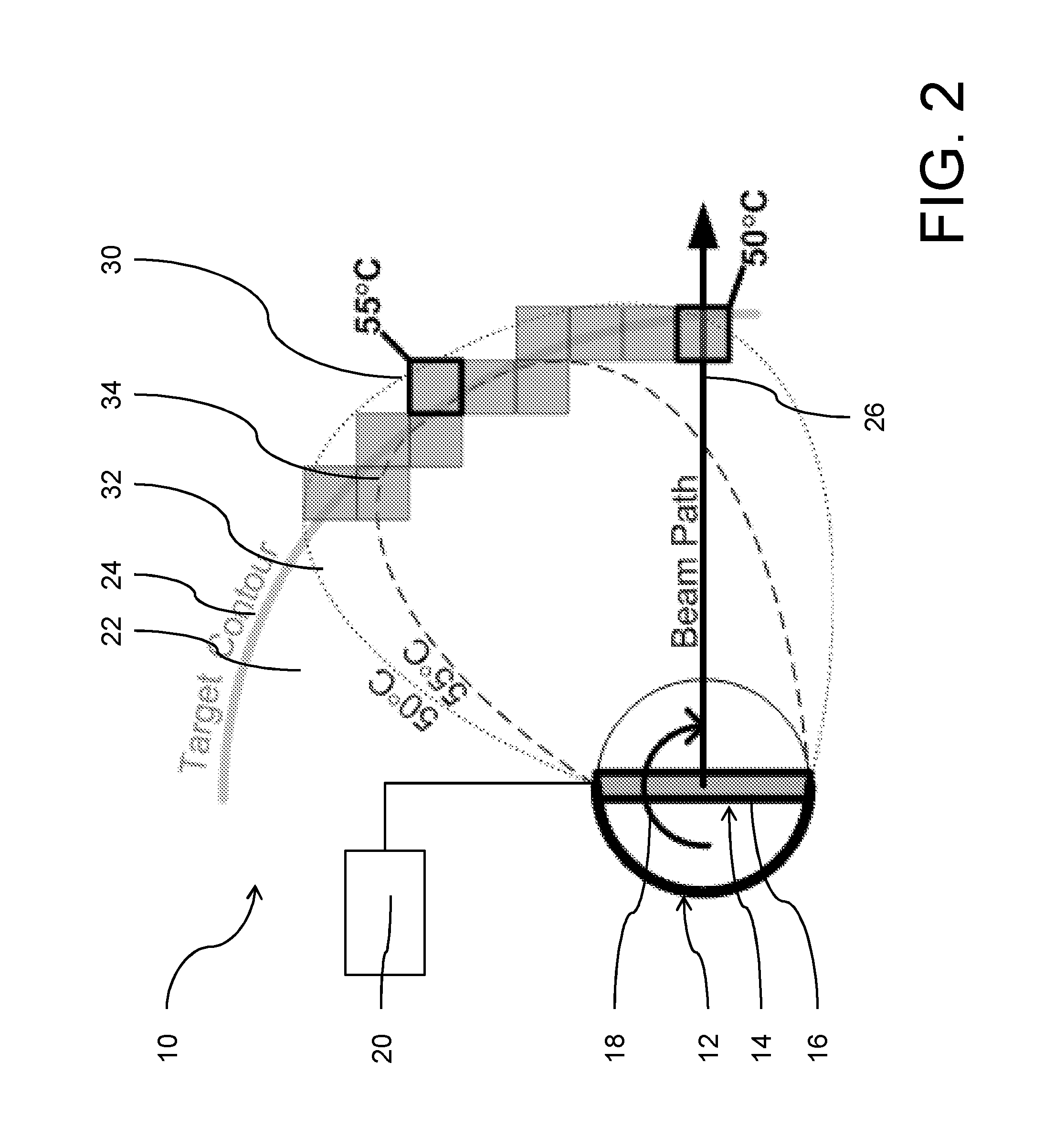
[0039]FIGS. 1 and 2 show an ultrasonic treatment device 10 according to a preferred embodiment. The ultrasonic treatment device 10 in this embodiment is an intra-urethral device a used for thermal treatments of the prostate.

[0040]The ultrasonic treatment device 10 comprises an ultrasonic irradiation unit 12 for generating high-intensity focused ultrasonic irradiation, also referred to as HIFU. The ultrasonic irradiation unit 12 comprises an ultrasonic transducer 14 for generating a beam path of ultrasonic irradiation, whereby the transducer 14 comprises an array of transducer elements 16, from which only one transducer element 16 is visible in FIGS. 1 and 2. The transducer elements 16 are arranged in a line along the longitudinal axis of the transducer 14. The ultrasonic transducer 14 is rotatable along its longitudinal axis.

[0041]The beam path of the ultrasonic irradiation has a width and includes areas affected to ultrasonic irradiation. The beam path has a direction, which refers...


PUM


Abstract

The present invention provides n ultrasonic treatment device (10) for heating a portion of a subject of interest, comprising a ultrasonic irradiation unit (12) for generating high-intensity focused ultrasonic irradiation, whereby a beam path of the ultrasonic irradiation is movable along a trajectory for depositing ultrasonic energy within a target zone (22) of the subject of interest, and a control unit (20) for controlling the ultrasonic irradiation unit (12) to move the beam path of the ultrasonic irradiation along the trajectory and to apply an ultrasonic dose to the target zone (22), wherein the control unit (20) is adapted to receive temperature information of the target zone (22) and to control the ultrasonic irradiation unit (12) based on the received temperature information, and the control unit (20) is adapted to control the ultrasonic irradiation unit (12) based on the temperature of a current (26) and at least one previous direction (28) of the beam path of the ultrasonic irradiation along the trajectory. The invention further provides a corresponding method for ultrasonic treatment and an ultrasonic treatment system, comprising the above ultrasonic treatment device (10) and a diagnostic imaging device for providing temperature information of a target zone (22) of the subject of interest, wherein the control unit (20) of the ultrasonic treatment device (10) is adapted to receive the temperature information from the diagnostic imaging device. By looking at the temperature or a thermal dose distribution along a previous direction of the beam path of the ultrasonic irradiation along the trajectory where the heating has been completed, an improved control of the treatment is achieved. Even if this previous sonication was different to the one currently applied, it represents a good indicator of the tissue and ultrasound system behavior.

Description

FIELD OF THE INVENTION[0001]The invention relates to the field of guided high-intensity focused ultrasound (HIFU) therapy.BACKGROUND OF THE INVENTION[0002]The invention pertains to guided high-intensity focused ultrasound (HIFU) therapy. An ultrasonic treatment device, i.e. a HIFU therapy module, directs the ultrasonic irradiation towards a target zone of a subject of interest, which is usually an alive being, more typically a human being.[0003]Interstitial and intraluminal ultrasonic irradiation devices frequently comprise a mechanically movable transducer, which enables a movement of a beam path of the ultrasonic irradiation. An exemplary application is the treatment of prostate cancer with a rotatable intra-urethral transducer. Accordingly, the transducer is movable so as to control the position within a target zone where HIFU energy is deposited. An actuator is provided to move the transducer. The actuator is controlled by a control unit to move, i.e. to rotate, the transducer, ...

Claims


Application Information

Patent Timeline
Patent Type & Authority Applications(United States)
IPC IPC(8): A61N7/02A61B5/01A61B8/13A61B5/055
CPCA61N7/02A61B5/015A61B2017/00084A61N2007/0078A61N2007/0082A61N2007/0095A61B5/055A61B34/10A61B8/13A61N2007/0091
Inventor MOUGENOT, CHARLES
Owner KONINKLJIJKE PHILIPS NV
Why Eureka
Try Eureka