
Method for controlling a drive system of a vehicle, a drive system, a computer program, a computer program product and a vehicle

a technology of drive system and vehicle, which is applied in the direction of vehicle sub-unit features, process and machine control, instruments, etc., can solve the problems of increasing fuel consumption and wear of the discs of the clutch, requiring a relatively large space in the vehicle, and the conventional clutch mechanism is also relatively heavy and costly. achieve the effect of reducing energy loss and increasing torqu

Active Publication Date: 2015-12-31
SCANIA CV AB
View PDF14 Cites 24 Cited by
  • Summary
  • Abstract
  • Description
  • Claims
  • Application Information

AI Technical Summary

Benefits of technology

This patent is about a method for controlling a drive system of a vehicle to allow it to be driven in environments where noise and exhaust levels from the combustion engine are not permission or desirable. The method reduces noise and exhausts gases from the vehicle by arranging the combustion engine in the inactive state, the braking device in the active state, and the planetary gear in the released state. The vehicle is then driven exclusively by the electrical machine, which provides higher torque and results in lower energy loss compared with prior art. The method also allows for faster operation of the electrical machine due to its higher rotational speed. The configuration of the drive system also prevents fatigue damage resulting from loading the same point of the planetary wheel axles. Overall, this method improves the performance and efficiency of the vehicle's drive system.

Problems solved by technology

There are disadvantages in using a conventional clutch mechanism that disconnects the input shaft of the gearbox from the combustion engine during a change of gears in the gearbox.
This heat results in increased fuel consumption and wear of the discs of the clutch.
A conventional clutch mechanism is also relatively heavy and costly.
It also requires a relatively large space in the vehicle.
The use of friction clutches results in energy losses.

Method used


Image

  • Method for controlling a drive system of a vehicle, a drive system, a computer program, a computer program product and a vehicle
  • Method for controlling a drive system of a vehicle, a drive system, a computer program, a computer program product and a vehicle
  • Method for controlling a drive system of a vehicle, a drive system, a computer program, a computer program product and a vehicle

Examples


Embodiment Construction

[0064]OF THE INVENTION

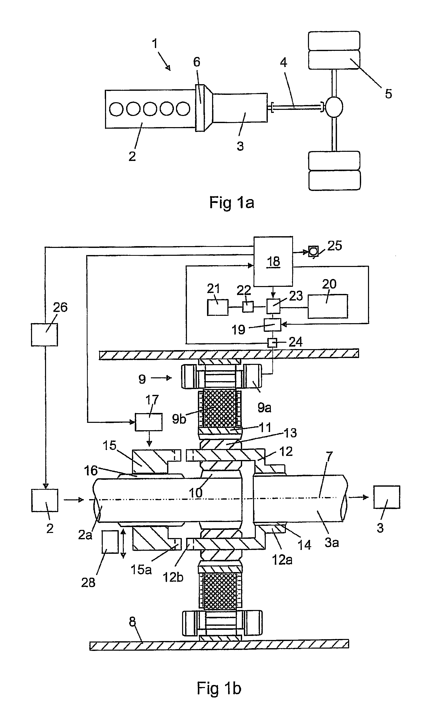
[0065]FIG. 1a discloses a driveline for a heavy vehicle 1. The driveline comprises a combustion engine 2, a gearbox 3, a plurality of drive shafts 4 and drive wheels 5. The drive line comprises an intermediate part 6 between the combustion engine 2 and the gearbox 3.

[0066]FIG. 1b discloses the components in the intermediate part 6 in detail. The combustion engine 2 is provided with an output shaft 2a and the gear box 3 is provided with an input shaft 3a in the intermediate part 6. The output shaft 2a of the combustion engine is coaxially arranged in relation to the input shaft 3a of the gearbox. The output shaft 2a of the combustion engine and the input shaft 3a of the gearbox are rotatably arranged around the axis 7. The intermediate part 6 comprises a housing 8 that encloses an electrical machine 9 and a planetary gear. The electrical machine 9 comprises in a stator 9a and a rotor 9b. The stator 9a comprises a stator core that is attached in suitable way on t...


PUM


Abstract

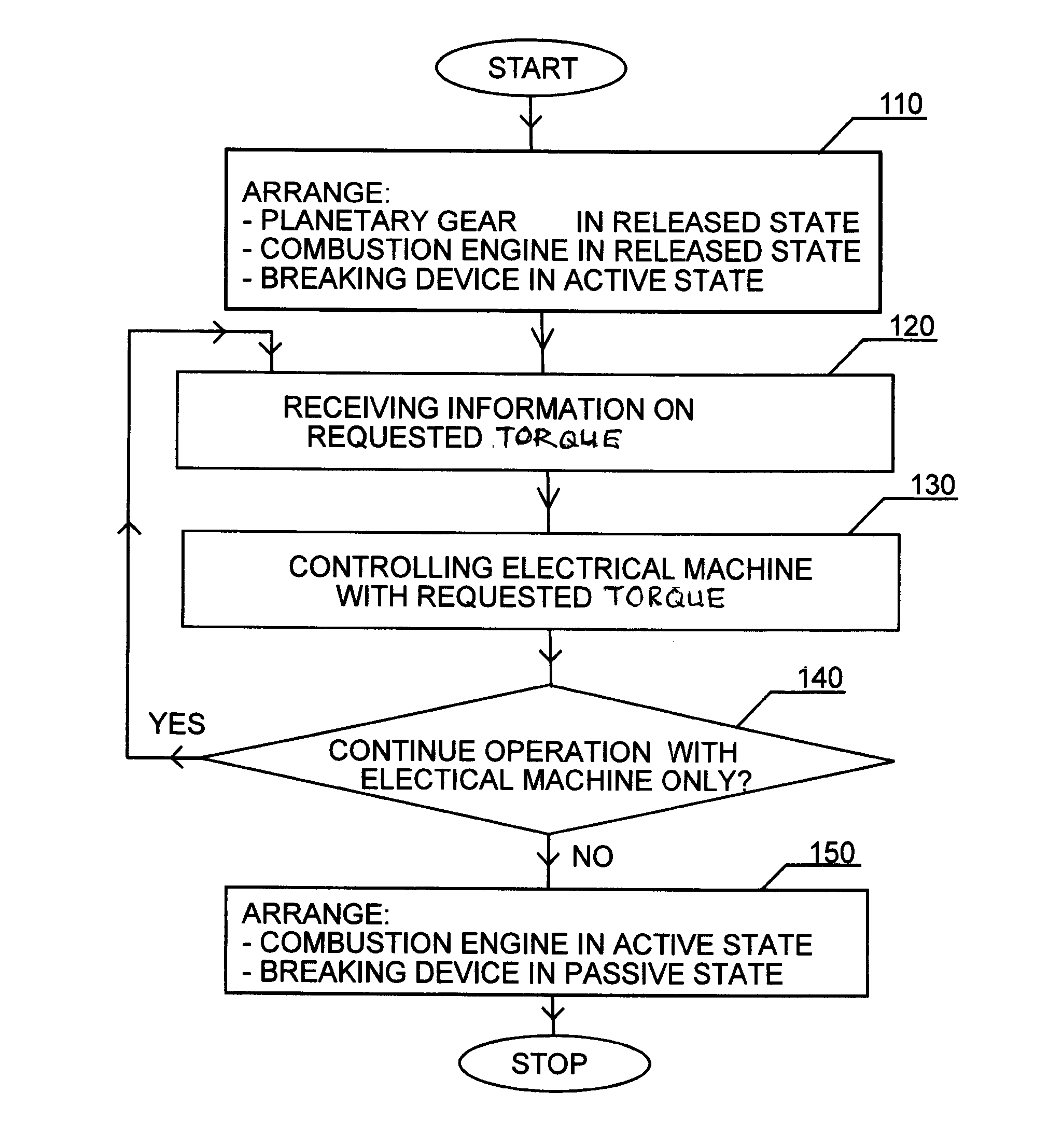
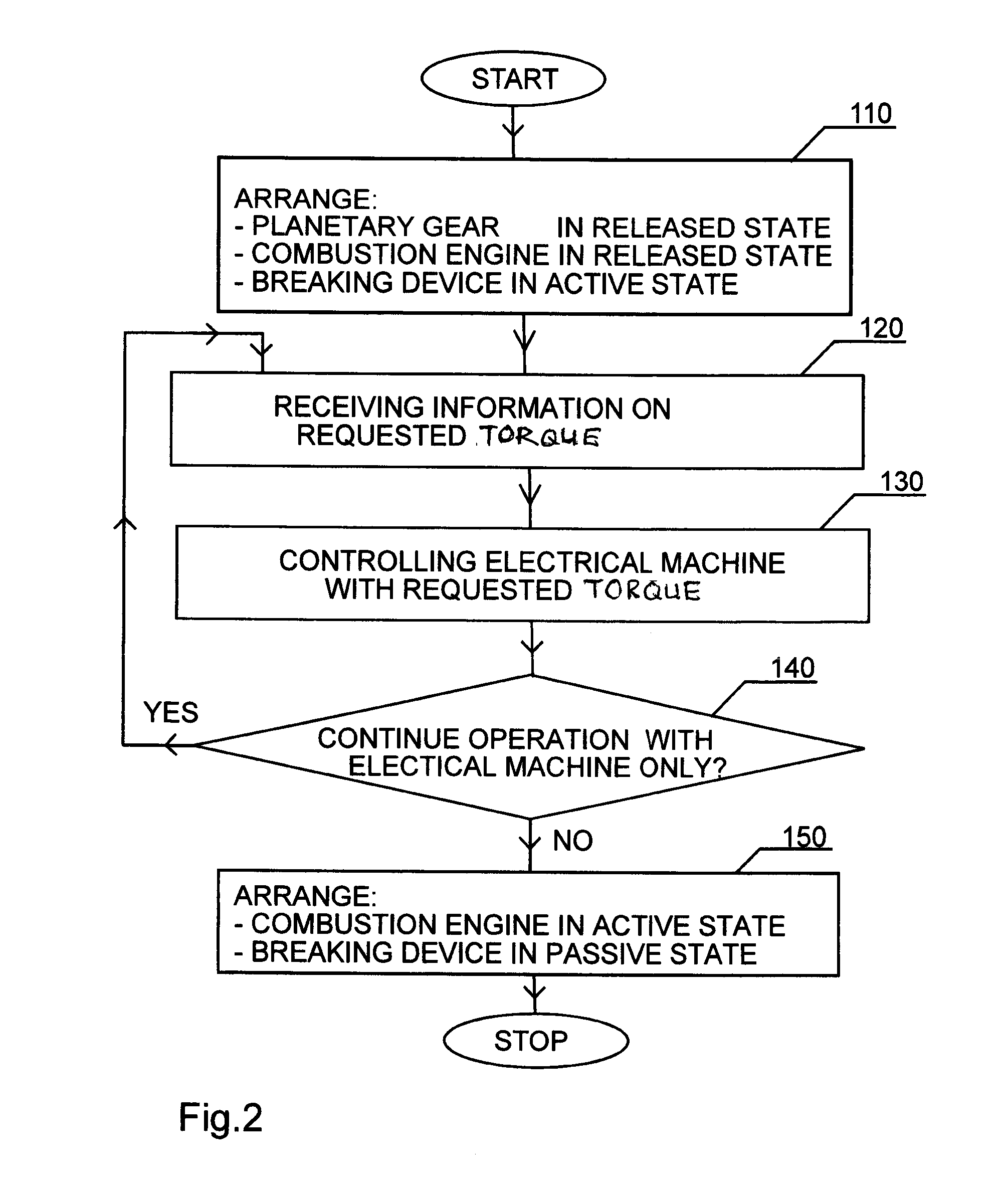
A method for controlling a drive system of a vehicle, the drive system including a combustion engine with an output shaft, a gearbox with an input shaft, an electrical machine including a stator and a rotor, and a planetary gear with a sun gear, a ring gear and a planet wheel carrier. The combustion engine may be active or inactive. A braking device may be active or passive. The planetary gear may be released or locked. The method includes arranging the planetary gear in the released state, the combustion engine in inactive state, the braking device in active state, and, when information on a requested torque for the operation of the vehicle is received, controlling the electrical machine to provide the requested torque with the combustion engine inactive, the braking device active and the planetary gear released.

Description

CROSS-REFERENCE TO RELATED APPLICATIONS[0001]The present application is a 35 U.S.C. §§371 National Phase conversion of PCT / SE2013 / 050789, filed Jun. 26, 2013, which claims priority of Swedish Patent Application No. 1250710-9, filed Jun. 27, 2012, the contents of which are incorporated by reference herein. The PCT International Application was published in the English language.TECHNICAL FIELD OF THE INVENTION[0002]The present invention relates to a method for controlling a drive system of a vehicle, in particularly a hybrid vehicle. The drive system comprises a combustion engine with an output shaft, a gearbox with an input shaft, an electrical machine that comprises a stator and a rotor, and a planetary gear that comprises a sun gear, a ring gear and a planet wheel carrier.[0003]The output shaft of the combustion engine is connected with a first of said components of the planetary gear so that they rotate as a unit with a first speed of rotation. The input shaft of the gearbox is co...

Claims


Application Information

Patent Timeline
IPC IPC(8): B60W20/00B60W10/18B60W10/10B60W10/06
CPCB60K6/365B60K2006/4841B60W10/06B60W20/00B60K6/387B60Y2400/421Y02T10/6221B60W20/40B60W10/18B60W10/115B60W10/10B60W10/02B60W20/14B60W20/16B60W20/17B60W10/08B60W10/11B60W2510/244B60W2520/04B60W20/13Y02T10/6286B60K2006/381B60K6/48Y02T10/62Y02T10/92
Inventor PETTERSSON, NIKLASBERGQUIST, MIKAELLINDSTRÖM, JOHANKJELL, ANDERSBJÖRKMAN, MATHIAS
Owner SCANIA CV AB
Learn More