Fuel and thermal management system

a technology of thermal management system and fuel, which is applied in the direction of combustion air/fuel air treatment, turbine/propulsion fuel heating, instruments, etc., can solve the problems of preventing the proper operation of components, and affecting the performance of aircra

Active Publication Date: 2015-12-31
HAMILTON SUNDSTRAND CORP
View PDF35 Cites 18 Cited by
  • Summary
  • Abstract
  • Description
  • Claims
  • Application Information

AI Technical Summary

Problems solved by technology

Operation of these systems degrades airplane performance through a combination of additional aerodynamic drag, parasitic losses, or increased weight.
However, the use of aircraft fuel as a heat sink has not found widespread acceptance in commercial aircraft systems due to a variety of factors.
A significant challenge to implementation of fuel-based thermal management systems on aircraft has been and continues to be the formation varnish or coke deposits on high temperature surfaces with which the fuel comes in contac...

Method used


Image

  • Fuel and thermal management system
  • Fuel and thermal management system
  • Fuel and thermal management system

Examples


Embodiment Construction

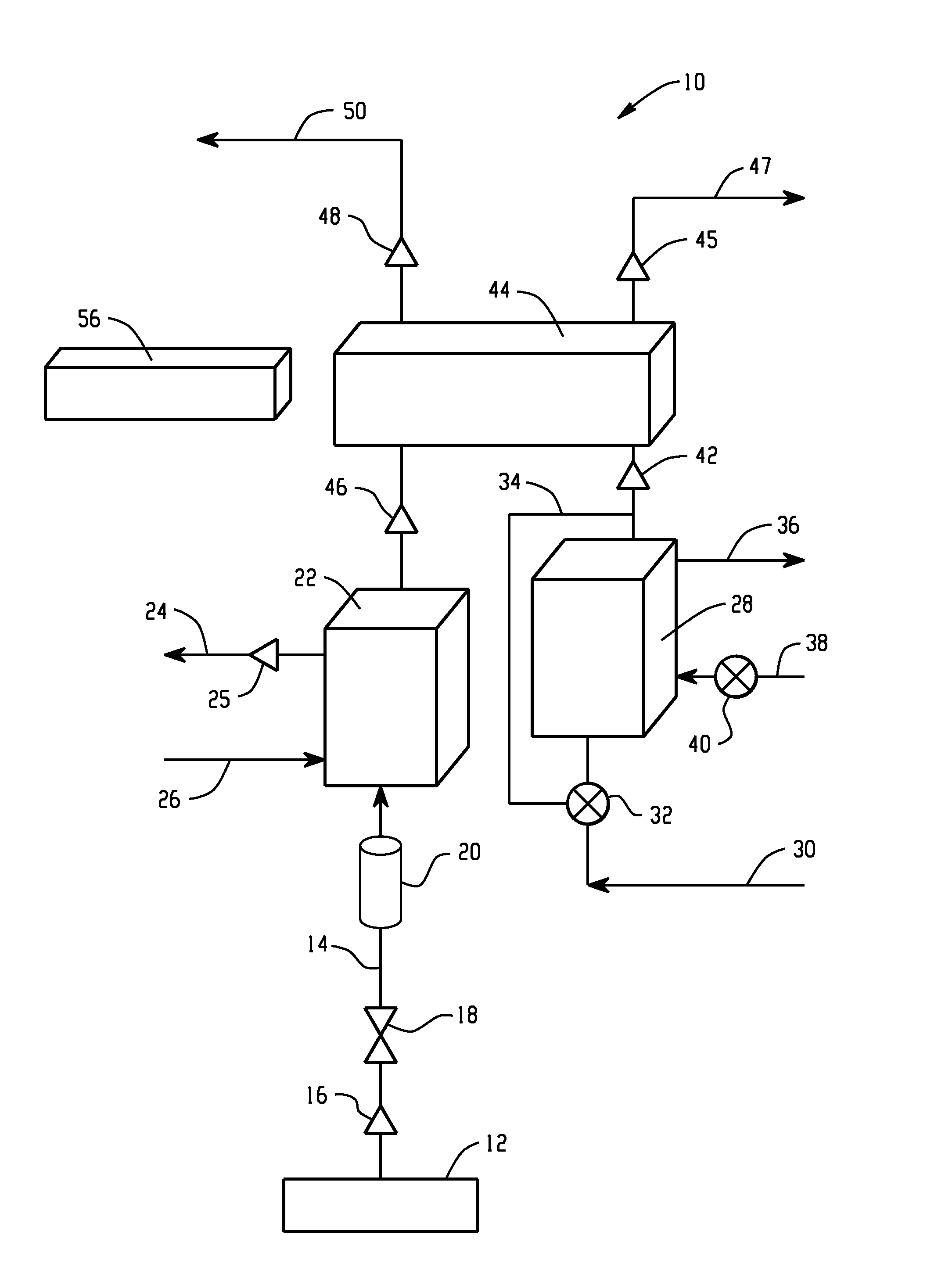
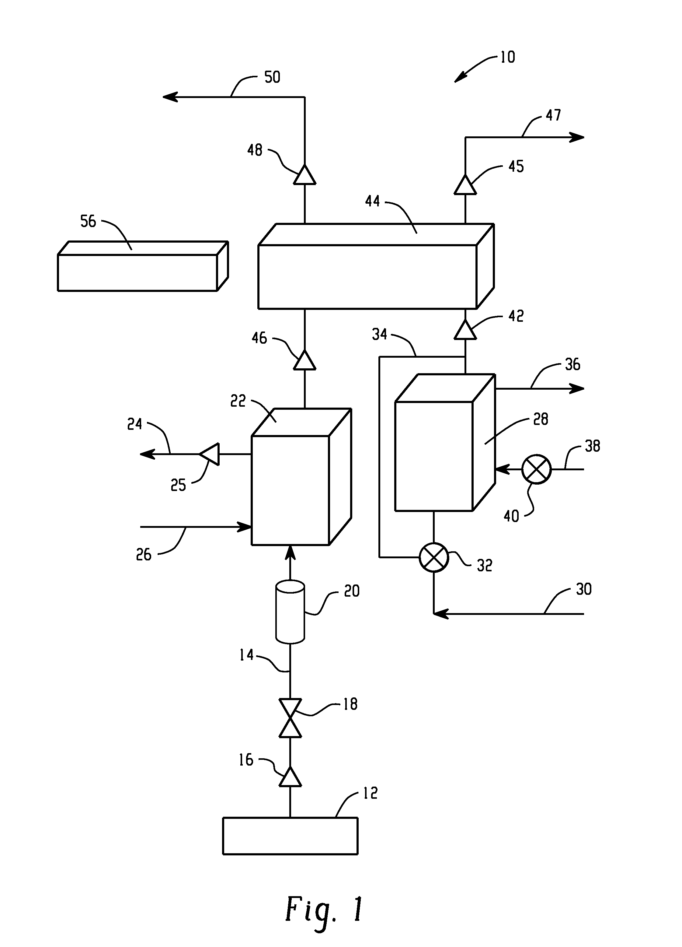
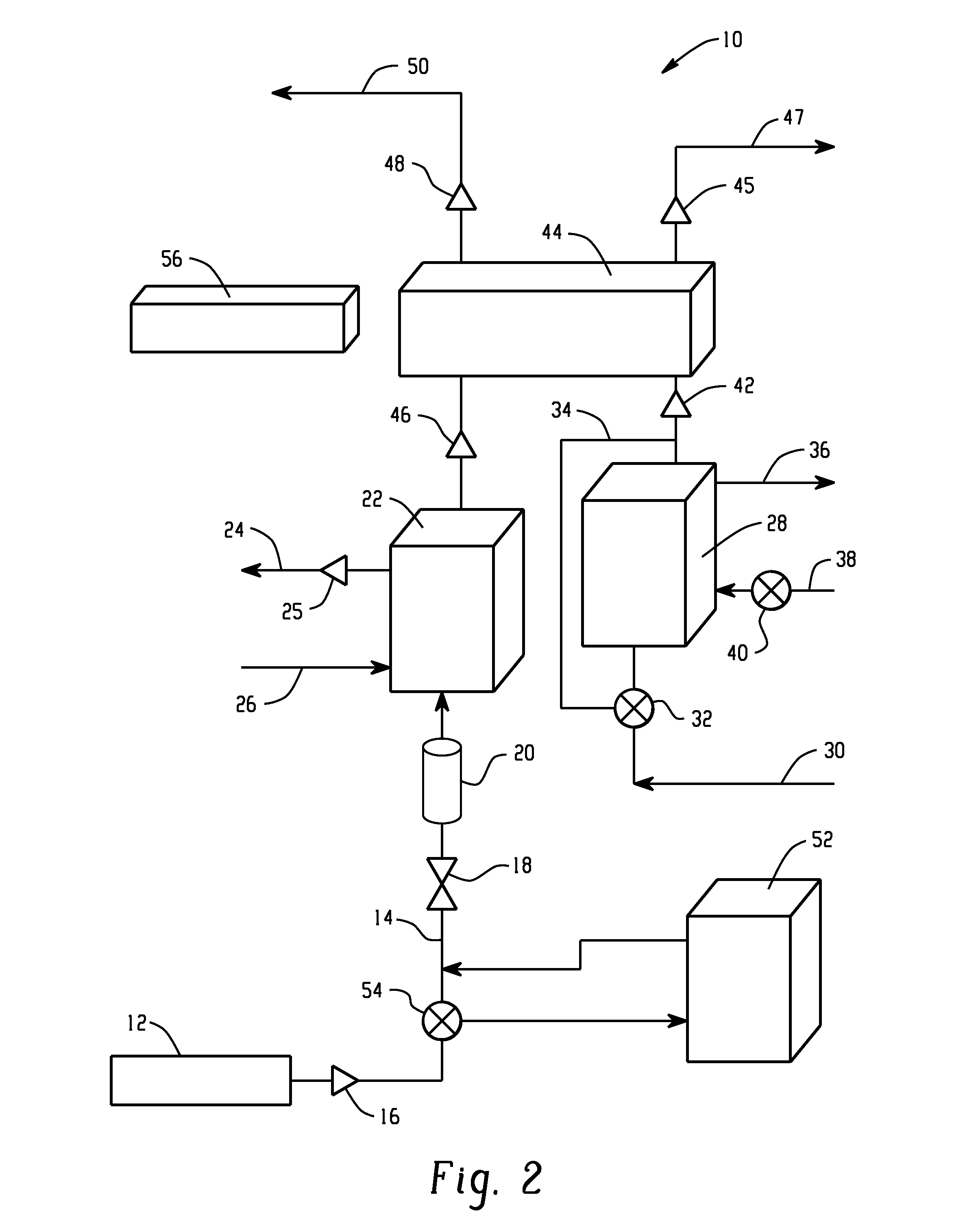
[0010]With reference to the Figures, FIGS. 1 and 2 schematically depict exemplary systems of the invention. As shown in FIGS. 1 and 2, exemplary fuel and thermal management systems 10 are shown with fuel tank 12 providing fuel through fuel line 14 having temperature sensor 16 and oxygen sensor 18 for measuring dissolved oxygen levels in the fuel. A flow meter 20 measures fuel flow rate of fuel entering the system 10. Fuel is delivered to optional heat exchanger 22, which transfers heat to the fuel from lubricating oil circulated to an electrical generator (not shown) through oil lines 24, 26 having oil temperature sensor 25, thus raising the temperature of the fuel. Optional heat exchanger 22 has separate sections in thermal communication with one another, with one of the sections accommodating oil circulating to the generator and another section accommodating fuel.

[0011]Lubricating oil from an engine (not shown) is circulated to a first heat exchanger 28 through oil inlet line 30 h...


PUM


Abstract

A system for fuel and thermal management of fuel delivered to an engine is disclosed. The system includes a supply of fuel in fluid communication with a fuel inlet of the engine, and an oxygen sensor for measuring dissolved oxygen content in the fuel is in fluid communication with the fuel. The fuel is heated by transferring heat from engine oil in a heat exchanger. The temperature of the fuel is controlled by controlling engine oil flow and airflow through another heat exchanger upstream of the fuel/oil heat exchanger on the oil circulation path with engine oil.

Description

BACKGROUND OF THE INVENTION[0001]Military and commercial aircraft utilize numerous engineered systems to control the temperature of heat sensitive components within the aircraft. These systems are designed to transfer heat from components or structures to air, fuel, or water based cooling media through heat exchangers. Operation of these systems degrades airplane performance through a combination of additional aerodynamic drag, parasitic losses, or increased weight. The use of aircraft fuel as a cooling media is the most efficient option as the rejected heat increases the enthalpy of the fuel which in turn has the potential to provide additional energy that can be thermodynamically recovered in the engine cycle.[0002]However, the use of aircraft fuel as a heat sink has not found widespread acceptance in commercial aircraft systems due to a variety of factors. A significant challenge to implementation of fuel-based thermal management systems on aircraft has been and continues to be t...

Claims


Application Information

Patent Timeline
IPC IPC(8): B64D37/34G05D7/06G05D23/19
CPCF02M31/125Y02T10/126G05D7/0641G05D23/19B64D37/34F01P11/08F02C7/224F02M31/10F02M31/16F02M31/20F01M2005/004F01P2003/006F01P2060/10F02D2200/0606F02D2200/0611F02D33/003Y02T50/671Y02T50/675F02C7/18Y02T10/12Y02T50/60
Inventor SMITH, PETER G.BOLT, CRAIG R.NIEMEYER, JONATHAN K.TILLMAN, THOMAS G.
Owner HAMILTON SUNDSTRAND CORP
Why Eureka
Try Eureka