Fuel injection system for internal combustion engine and control method for internal combustion engine

a technology of internal combustion engine and control method, which is applied in the direction of electric control, machines/engines, mechanical equipment, etc., can solve the problems of deteriorating the effect of improving exhaust properties and affecting so as to improve exhaust properties and reduce the accuracy of micro injection

Active Publication Date: 2015-12-31
TOYOTA JIDOSHA KK
View PDF5 Cites 11 Cited by
  • Summary
  • Abstract
  • Description
  • Claims
  • Application Information

AI Technical Summary

Benefits of technology

[0007]The range of the injection amount allowing injection accuracy to be ensured is narrower in the partial lift injection described above than in full lift injection allowing the needle valve to be fully opened. Accordingly, the injection accuracy of the micro injection m

Problems solved by technology

This may deteriorate the effect of improvement of exhaust properties.
Accordingly, the accuracy of the micro injection may be a

Method used


Image

  • Fuel injection system for internal combustion engine and control method for internal combustion engine
  • Fuel injection system for internal combustion engine and control method for internal combustion engine
  • Fuel injection system for internal combustion engine and control method for internal combustion engine

Examples


first embodiment

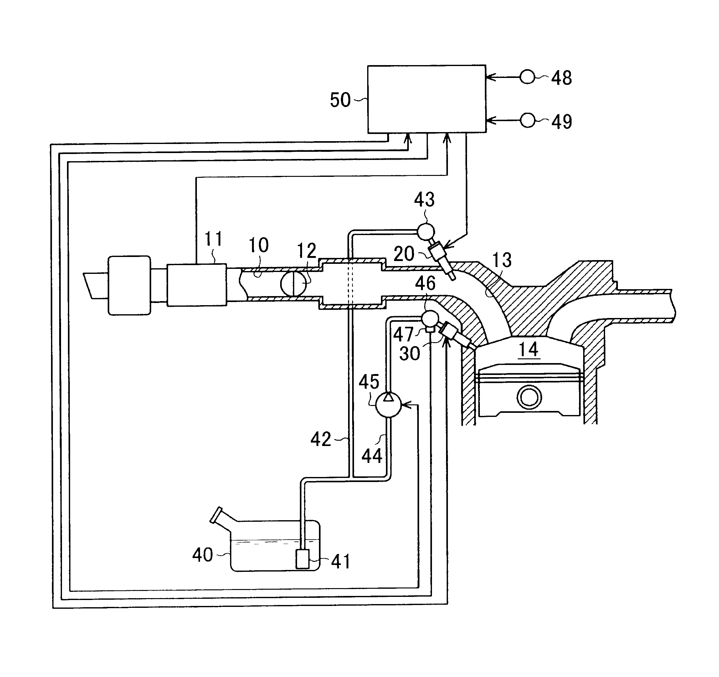
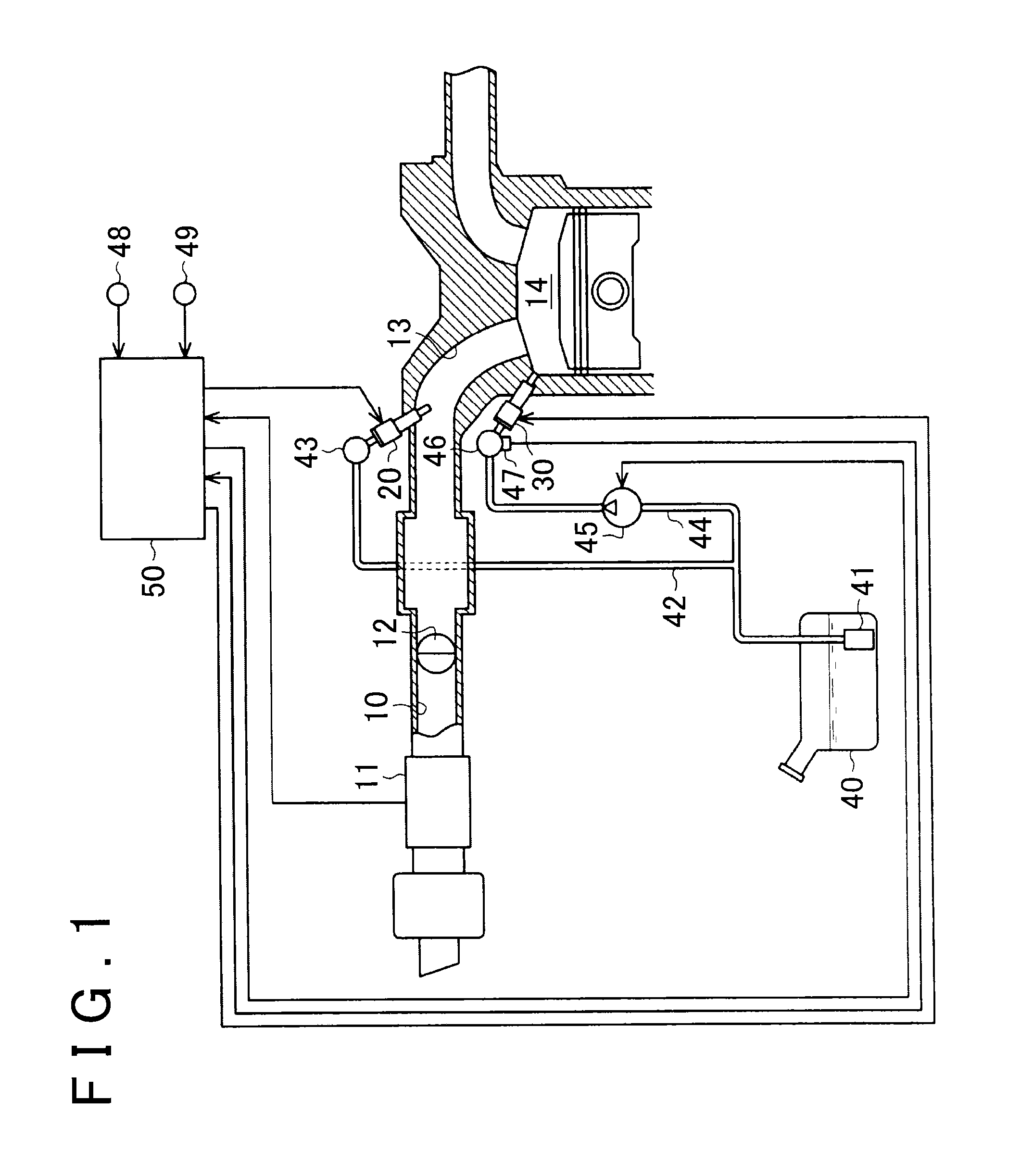
[0024]Hereinafter, a fuel injection system for an internal combustion engine will be described in detail with reference to FIGS. 1 to 5. As illustrated in FIG. 1, an air flow meter 11 and a throttle valve 12 are disposed, in order from an upstream side of an intake passage 10, in the intake passage 10 of an internal combustion engine. The air flow meter 11 is configured to detect an intake air amount. The throttle valve 12 is configured to adjust the intake air amount. The intake passage 10 branches on a downstream side of the throttle valve 12 and is connected to combustion chambers 14 for respective cylinders via intake ports 13.

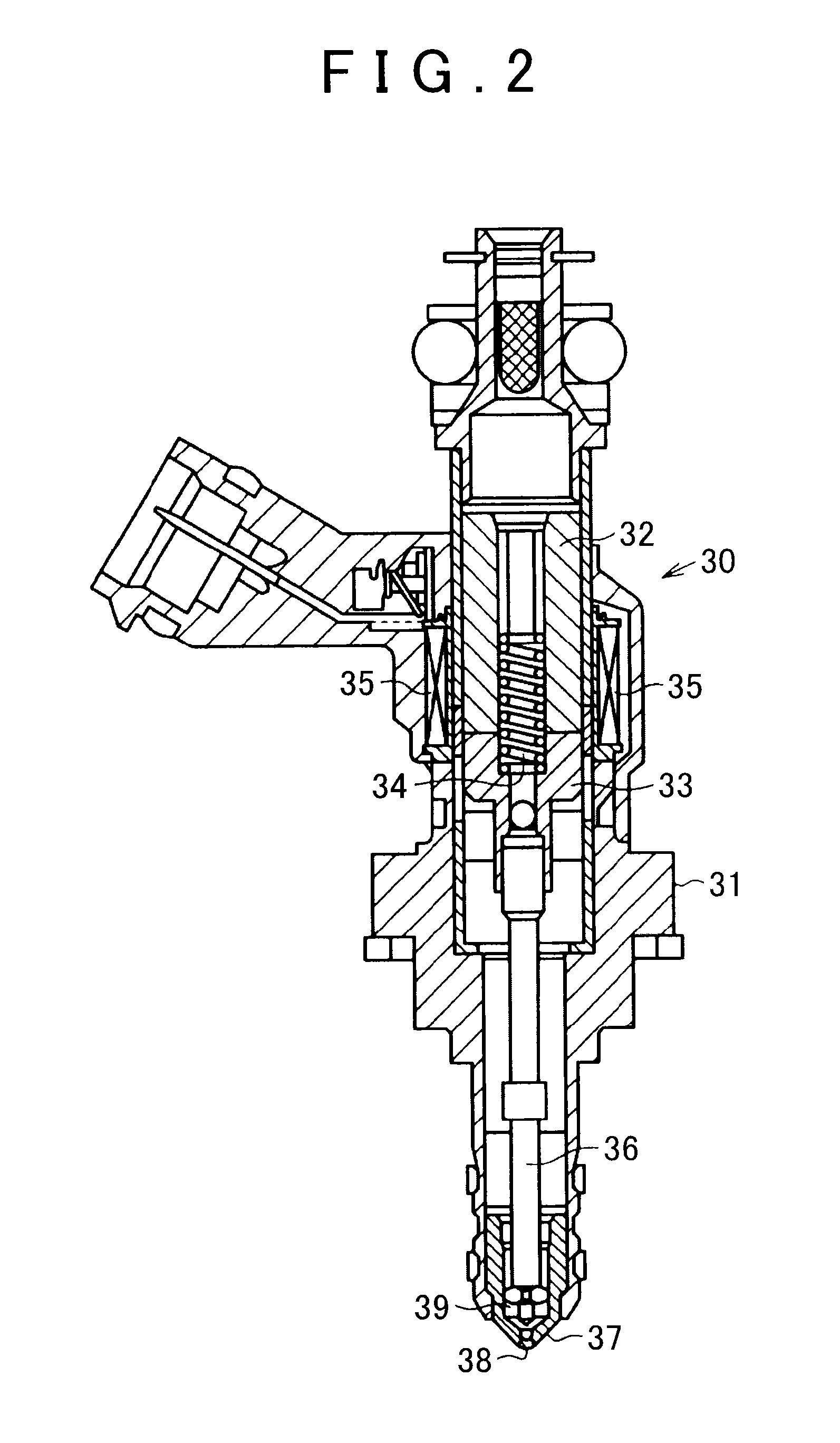
[0025]The fuel injection system for an internal combustion engine according to this embodiment is provided with two types of injectors, one being port injectors 20 and the other being in-cylinder injectors 30. The port injectors 20 for fuel injection into the intake ports 13 are arranged in the respective intake ports 13 for the respective cylinders. The i...

second embodiment

[0071]FIGS. 6A to 6F illustrate a change in the manner of implementation of the fuel injection following the amount-decreasing correction for the required injection amount in the partial lift injection region according to the In FIGS. 6A to 6F, [DI] represents in-cylinder injection and [PFI] represents port injection. In the following description, the [DI] is attached to the end of a sign for the injection amount relating to in-cylinder injection and the [PFI] is attached to the end of a sign for the injection amount relating to port injection so that the types of the injection are distinguished from each other.

[0072]As illustrated in FIG. 6B, each of the P / L injection amount Qp[DI] and the F / L injection amount QF[PFI] is set, so that the sum of the P / L injection amount Qp[D] and the F / L injection amount QF[PFI] becomes equal to the required injection amount Q, in a case where the correction of the required injection amount Q is not required in the partial lift injection region. Th...


PUM


Abstract

A fuel injection system for an engine, the fuel injection system includes injectors and an electronic control unit. The injectors include needle valves; and the ECU is configured to: (i) execute partial lift injection and full lift injection with the injectors, the partial lift injection being injection during which the needle valve does not reach a fully-open state and the full lift injection being injection during which the needle valve reaches the fully-open state; (ii) operate the engine in a partial lift injection region where the injection of a required injection amount of a fuel is shared by the partial lift injection and the full lift injection; and (iii) perform the amount of correction of the required injection amount with respect to the injection amount shared by the full lift injection when the required injection amount is corrected while the engine is operated in the partial lift injection region.

Description

INCORPORATION BY REFERENCE[0001]The disclosure of Japanese Patent Application No. 2014-130371 filed on Jun. 25, 2014 including the specification, drawings and abstract is incorporated herein by reference in its entirety.BACKGROUND OF THE INVENTION[0002]1. Field of the Invention[0003]The invention relates to a fuel injection system for an internal combustion engine and a control method for an internal combustion engine.[0004]2. Description of Related Art[0005]Some fuel injection systems for internal combustion engines perform micro fuel injection in order to improve exhaust properties. In improving the accuracy of the micro injection, an irregularity may arise in the injection amount of an injector. Bouncing occurring when a needle valve is fully open is one of the factors causing the irregularity of the injection amount of the injector. The effect of the bouncing of the needle valve on the injection accuracy relatively increases as the injection amount decreases. Accordingly, a lowe...

Claims


Application Information

Patent Timeline
IPC IPC(8): F02D41/30F02M61/10F02D41/26F02M51/06
CPCF02D41/3094F02D41/32F02D41/402F02D2041/389F02D2200/063F02M69/046F02D2200/101F02D41/3005F02D41/26Y02T10/44F02M63/029F02D2200/1002Y02T10/40
Inventor HIGUCHI, AKIHIKONAKANO, TOMOHIROKANEKO, RIHITOMURASE, EIJI
Owner TOYOTA JIDOSHA KK
Why Eureka
Try Eureka