Multi-channel guided wave radar level gauge

a radar level gauge and guided wave technology, applied in the direction of using reradiation, liquid/fluent solid measurement, coupling device, etc., can solve the problems of material clogging and mechanical strength, increased resistive losses, and inconvenient use of radar level gauges using antennas to provide free propagating signals. , to achieve the effect of reducing mutual interference, safe operation and efficient manufactur

Active Publication Date: 2015-12-31
ROSEMOUNT TANK RADAR
View PDF25 Cites 16 Cited by
  • Summary
  • Abstract
  • Description
  • Claims
  • Application Information

AI Technical Summary

Benefits of technology

[0023]The provision of sufficient isolation between the circuitry arrangements ensures little or no leakage between the channels. As a consequence, it is not necessary that the first and second electromagnetic signals are distinguishable from each other. In fact, according to a preferred embodiment, the first and second electronics units are designed to transmit substantially identical electromagnetic signals, i.e. signals having the same frequency and amplitude behavior. It is noted that the two circuitry arrangements typically are not used exactly simultaneously. However, the design according to the invention intends to minimize mutual interference. Even if the two arrangements are used in different overall systems (such as level measurement and overfill detection) interference needs to be avoided.
[0024]In this case the circuitry arrangements may be functionally identical, and most preferably multiple samples from the same manufacturing process. This makes the system efficient to manufacture. Two substantially identical units are simply connected to the power divider, which is connected to the single line transmission line probe via the matching arrangemen...

Problems solved by technology

However, in some applications radar level gauges using antennas to provide free propagating signals are not suitable, and a wave guiding structure is used to guide the waves.
A too small diameter will increase resistive losses and may cause problems with material clogging and mechanical strength.
However, in recent years, the cost for the mechanical installation of a radar level gauge has increased faster than the cost for the electronics in the gauge.
This requirement has so far in practice limited the available solutions for connecting several gauges to a single propagating device to solutions involving different and distinguishable signals or propagation modes.
If a single wire probe is used there ...

Method used


Image

  • Multi-channel guided wave radar level gauge
  • Multi-channel guided wave radar level gauge
  • Multi-channel guided wave radar level gauge

Examples


Embodiment Construction

[0033]In the present detailed description, various embodiments of the radar level gauge system according to the present invention are mainly discussed with reference to radar level gauge systems using pulsed signals and filling level determination by means of measuring the time between transmitted and reflected pulses. However, the teachings of the present invention are potentially also applicable using other radar techniques. When pulses modulated on a carrier are used, phase information can also be utilized.

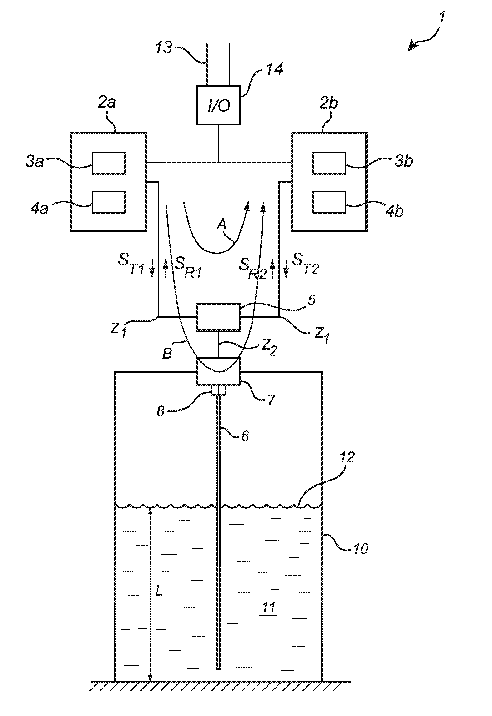
[0034]FIG. 1 schematically illustrates a radar level gauge system 1 according to an embodiment of the present invention, comprising at least two measurement electronics units 2a, 2b, each including a circuitry arrangement with transceiver circuitry 3a, 3b connected to processing circuitry 4a, 4b. Each transceiver circuitry 3a, 3b is connected to a power divider 5 which will be described in more detail below. The power divider is connected to a single wire transmission line prob...


PUM


Abstract

A level gauge for detecting process variables related to a distance to a surface of a content in a tank, comprising a first and second functionally independent circuitry arrangements comprising transceiver circuitry and processing circuitry. The gauge further comprises a power divider providing isolation between signals having the same propagation mode, a single wire transmission line probe, and a matching arrangement providing an electrically matched connection between the electrical connection of a process seal and the single wire transmission line probe.
A combination of a power divider with a matching arrangement allows multiple channels on one single wire transmission line probe.

Description

FIELD OF THE INVENTION[0001]The present invention relates to a multi-channel radar level gauge using electromagnetic waves guided by a guided wave probe into a tank to determine a distance to a surface of a product in the tank.BACKGROUND OF THE INVENTION[0002]Radar level gauging (RLG) is an increasingly important method for level gauging in tanks, containers, etc. A radar level gauge typically includes transceiver circuitry and processing circuitry which is connected to a propagation device adapted to allow propagation of electromagnetic signals into the tank. An example of such a systems is disclosed in U.S. Pat. No. 7,106,247 by the same applicant.[0003]The signal propagating device may be a directional antenna. However, in some applications radar level gauges using antennas to provide free propagating signals are not suitable, and a wave guiding structure is used to guide the waves. Based on propagation mechanism three different types of wave guiding structures are known in the p...

Claims


Application Information

Patent Timeline
IPC IPC(8): G01F23/284
CPCG01F23/284H01P5/16H01Q1/225G01S7/4017G01F23/0069G01S13/88G01S7/292H01Q1/50G01F23/802G01F25/00G01S13/87H01Q13/20
Inventor EDVARDSSON, OLOV
Owner ROSEMOUNT TANK RADAR
Why Eureka
Try Eureka