Maintenance checking system and method for dental handpiece, and system and method for controlling drive motor

a handpiece and maintenance check technology, applied in the field of dental handpiece maintenance check system and method, can solve the problems of user inability to decide whether to do the maintenance of the handpiece or not, abnormal heat generation, etc., to prevent abnormal heat generation, increase the load of the drive motor, and prevent excess heat generation

Active Publication Date: 2015-12-31
NAKANISHI INC
View PDF4 Cites 6 Cited by
  • Summary
  • Abstract
  • Description
  • Claims
  • Application Information

AI Technical Summary

Benefits of technology

[0037]According to the present invention, the maintenance condition of a handpiece is deduced from the no-load current value of the motor to which the handpiece is connected, and the no-load current value is converted to a coefficient and used for controlling the drive motor so that the handpiece, if not usable, will not increase the load of the drive motor, to thereby prevent abnormal heat generation. Thus, even if an insufficiently maintained or unusable dental handpiece is used, the drive time of the drive motor is limited to prevent excess heat generation in the handpiece.

Problems solved by technology

With a dental tool rotating at as such a high speed as 200000 rpm, proper maintenance, such as cleaning or lubricating, of the dental tool keeps the handpiece from abnormal heat generation, but absence of proper maintenance may result in attachment of dust or contaminants, or lubricant shortage in the driving section of the handpiece, including gears and bearings, which may cause abnormal heat generation.
However, this system cannot inform the user, before starting the operation, whether the handpiece parts connected to the micromotor are properly maintained, or the handpiece is appropriate for use, so that the user cannot decide whether to do the maintenance of the handpiece or not.

Method used


Image

  • Maintenance checking system and method for dental handpiece, and system and method for controlling drive motor
  • Maintenance checking system and method for dental handpiece, and system and method for controlling drive motor
  • Maintenance checking system and method for dental handpiece, and system and method for controlling drive motor

Examples


Embodiment Construction

[0046]The present invention will now be explained in detail with reference to FIGS. 1 to 8.

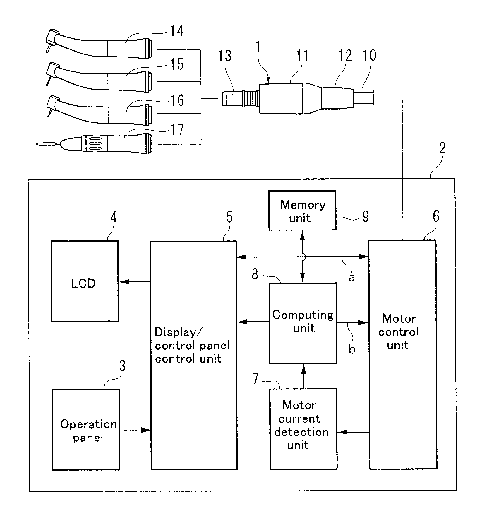
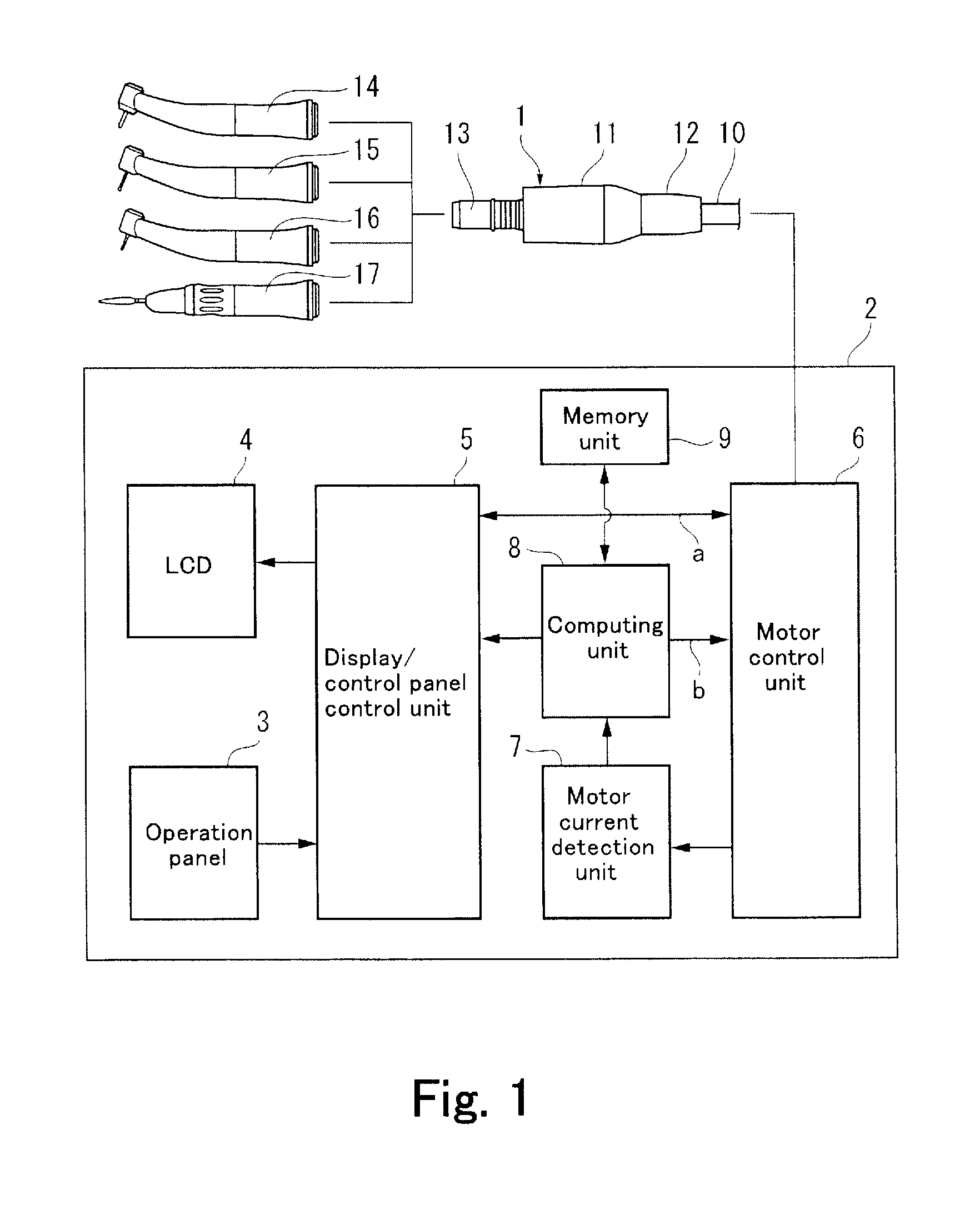
[0047]FIG. 1 is a block diagram illustrating an embodiment of the motor control system for a dental handpiece according to the present invention. The motor control system includes drive motor 1 and control system 2 for checking and controlling the motor 1.

[0048]The motor 1 has body 11, electrical cord connecting part 12 at the proximal end of the body 11, and handpiece coupling part 13 at the distal end of the body 11. To the electrical cord connecting part 12 is connected electrical cord 10 to provide electrical connection of the motor 1 to the control system 2, which is connected to a power source. To the handpiece coupling part 13, one of the various handpieces, e.g., contra-angle handpieces 14, 15, 16 and straight handpiece 17, is to be connected selectively. In this embodiment, the contra-angle handpiece 14 is a speed-increasing handpiece with the speed increasing ratio of 1:5 with respec...


PUM


Abstract

A method for maintenance checking of a dental handpiece is disclosed. The method comprises measuring in advance no-load current values of a drive motor, with a handpiece known as being in usable condition and a handpiece known as insufficiently maintained respectively connected thereto and operated in no-load condition, storing as reference data the no-load current values of the drive motor together with associated data relating to degree of maintenance, measuring a no-load current value of the drive motor with a dental handpiece to be checked connected thereto and operated in no-load condition, and determining whether the handpiece checked is usable, requires maintenance, or is unusable, by comparing the measured no-load current value with the reference data.

Description

[0001]This application claims priority to Japanese Patent Application No. 2014-129780, filed Jun. 25, 2014, the entire disclosure of which is hereby incorporated by reference herein.FIELD OF ART[0002]The present invention relates to maintenance checking system and method for a dental handpiece, that are intended for protecting a dental handpiece, such as a motor-driven, straight or contra-angle handpiece, from damages caused by heat generation in high-speed rotation due to insufficient maintenance of the handpiece, as well as system and method for controlling a drive motor for a dental handpiece.BACKGROUND ART[0003]In the art of dentistry, a dental handpiece is attached to and driven by a motor, of which rotation is transmitted through a train of gears to a dental tool, such as a cutting bur, at the tip of the handpiece for cutting teeth. There are a variety of trains of gears, such as for multiplying the rotation speed up to five times, transmitting the rotation at a direct ratio, ...

Claims


Application Information

Patent Timeline
Patent Type & Authority Applications(United States)
IPC IPC(8): G01R31/34A61C1/00
CPCG01R31/343A61C1/003
Inventor MUTO, SHINICHIROUISHIJIMA, MASARUYOKOCHI, KEITAMATSUSHITA, HAYATOUEKI, YUKIHIRO
Owner NAKANISHI INC
Why Eureka
Try Eureka