Liquid crystal display device

a liquid crystal display and display device technology, applied in non-linear optics, instruments, optics, etc., can solve the problems of narrow visual angle of liquid crystal display, serious visual angle light leakage, visual angle asymmetry, etc., and achieve the effect of wide and more symmetrical and less light leakag

Inactive Publication Date: 2015-12-31
INNOLUX CORP
View PDF1 Cites 1 Cited by
  • Summary
  • Abstract
  • Description
  • Claims
  • Application Information

AI Technical Summary

Benefits of technology

[0010]In the liquid crystal display device of the present invention, the visual angle asymmetry and the light leakage caused by the pre-tilt angle of the first liquid crystal layer (i.e. the inclined angle formed between the first polarizer and the long axis of the liquid crystal molecules in the first liquid crystal layer) have been significantly improved through applying the compensation member. The complementary types of the liquid crystals in the compensation member and the first liquid crystal layer have been used. The thickness, the pre-tilt angle of the second liquid crystal layer (i.e. the inclined angle formed between the first polarizer and the short axis of the liquid crystal molecules in the second liquid crystal layer), and the disposed position of the compensation member have been selectively adjusted. The resulting liquid crystal display device of the present invention has visual angles that are wider and more symmetrical with lesser light leakage.

Problems solved by technology

However, the common flaw of liquid crystal display is its narrow visual angle.
This pre-tilt angle will cause visual angle asymmetry and serious visual angle light leakage in the dark state, low contrast in visual angle, and other flaws of liquid crystal display.
However, these solutions still cannot address the above problems effectively.

Method used


Image

  • Liquid crystal display device
  • Liquid crystal display device
  • Liquid crystal display device

Examples


example 1

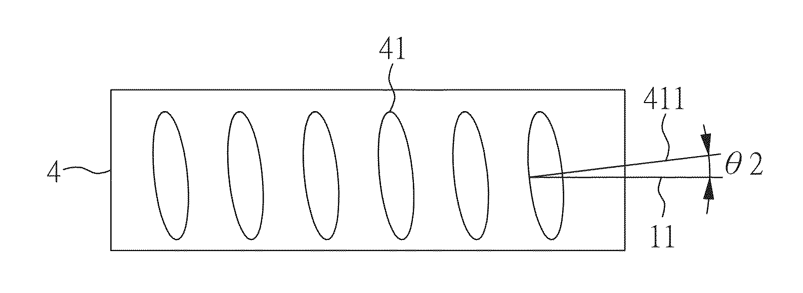
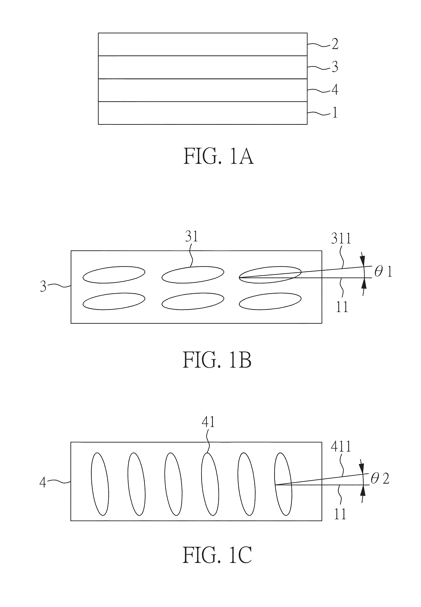
[0022]FIG. 1A is a schematic diagram of a liquid crystal display device of a preferred embodiment of the present invention. The liquid crystal display device includes: a first polarizer 1; a second polarizer 2 corresponding to the first polarizer 1; a liquid crystal panel disposed between the first polarizer 1 and the second polarizer 2, the liquid crystal panel comprising a first liquid crystal layer 3 having a first aligning direction; and a compensation member disposed between the first polarizer 1 and the second polarizer 2. The compensation member comprises a second liquid crystal layer 4, and the compensation member is on the liquid crystal panel. In the present example, the compensation member is disposed between the first polarizer 1 and the first liquid crystal layer 3 and is attached on the liquid crystal panel. However, the compensation member may also be disposed between the second polarizer 2 and the first liquid crystal layer 3.

[0023]Referring to FIGS. 1B and 1C, they ...

example 2

[0035]FIG. 3 is a schematic diagram of a liquid crystal display device according to another embodiment of the present invention. In addition to a commercial visual angle compensation film 5 (in the present example, NAZ270 compensation film is used) disposed between the first polarizer 1 and the compensation member 4, all the other elements are the same as that of the liquid crystal display device of FIG. 1A in Example 1. Thus, the description of the parts that are the same as Example 1 are omitted.

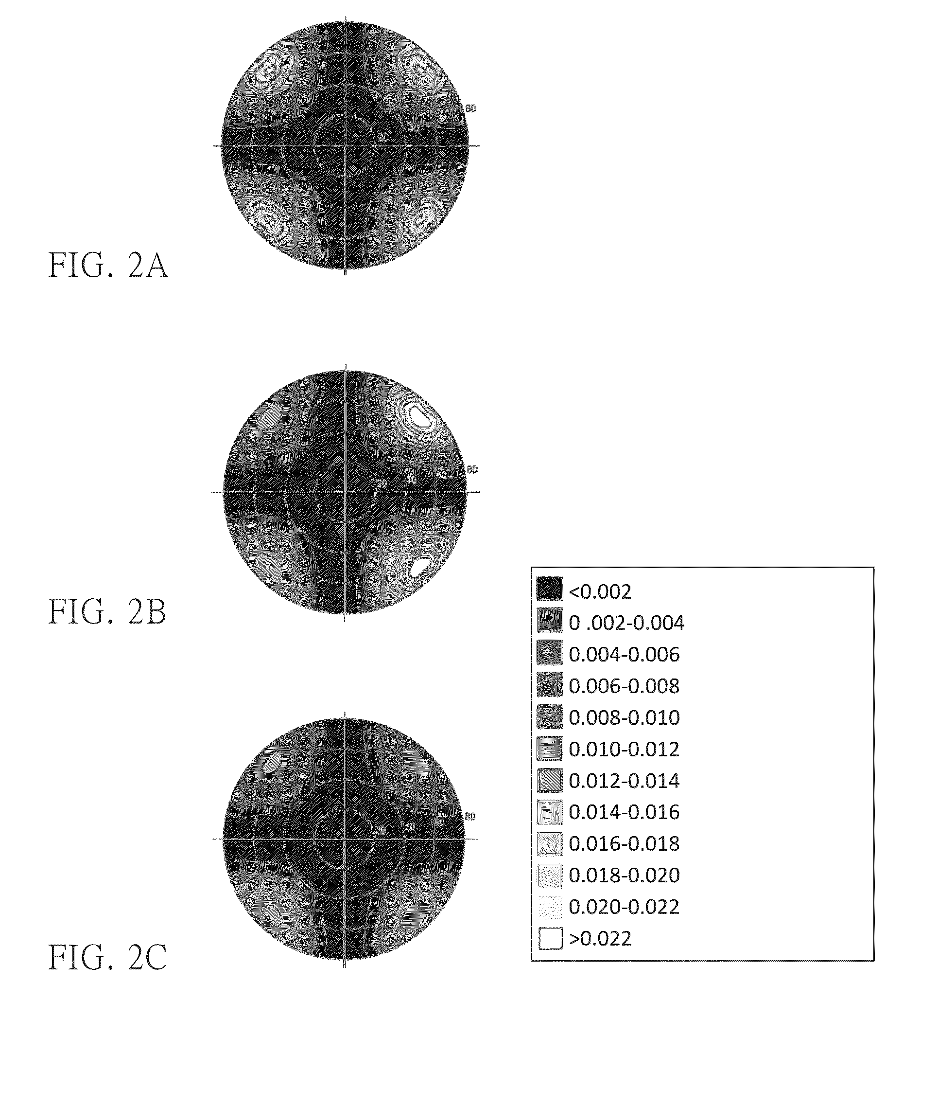
[0036]FIGS. 4A to 4C are the test results of the light leakage in the dark state of the liquid crystal display device. The tests are performed under the state that a light with a single wavelength of 550 nm is irradiated to a liquid crystal display device from the side of the first polarizer 1.

[0037]In FIG. 4A, the commercial visual angle compensation film 5 is disposed in the liquid crystal display device and the first liquid crystal layer 3 of the liquid crystal panel does not have a pre...

example 3

[0039]FIG. 5 is a schematic diagram of a liquid crystal display device according to another embodiment of the present invention. In the present example, the influences caused by an incident light with multi-wavelength and other films of the liquid crystal panel are further explored. The liquid crystal panel may further include a thin-film transistor (TFT) substrate 6 disposed between the first liquid crystal layer 3 and the compensation member 4 and a color filter substrate 7 disposed between the first liquid crystal layer 3 and the second polarizer 2. In addition to the above-mentioned elements, all the other elements are the same as that of the liquid crystal display device of FIG. 3 in Example 2. Thus, the descriptions of the parts that are the same as Example 2 are omitted.

[0040]In the present example, in FIG. 5, the detailed structure of the TFT substrate 6 is omitted including a gate, an insulated layer, a semiconductor layer, a source, and a drain. Also, the detailed structur...


PUM

PropertyMeasurementUnit
angleaaaaaaaaaa
alignment angle calculationaaaaaaaaaa
inclined angleaaaaaaaaaa

Abstract

A liquid crystal display device is disclosed, which comprises: a first polarizer; a second polarizer corresponding to the first polarizer; a liquid crystal panel disposed between the first polarizer and the second polarizer, the liquid crystal panel comprises a first liquid crystal layer having a first alignment direction; and a compensation member disposed between the first polarizer and the liquid crystal panel or between the second polarizer and the liquid crystal panel, the compensation member is attached on the liquid crystal panel, and the compensation member comprises a second liquid crystal layer having a second alignment direction; wherein the first and second alignment directions are substantially the same and the dielectric anisotropies of the first and second liquid crystals are the opposite.

Description

CROSS REFERENCE TO RELATED APPLICATION[0001]This application claims the benefits of the Taiwan Patent Application Serial Number 103122042, filed on Jun. 26, 2014, the subject matter of which is incorporated herein by reference.BACKGROUND OF THE INVENTION[0002]1. Field of the Invention[0003]The present invention relates to a liquid crystal display device and, more particularly, to a liquid crystal display device in which the visual angle asymmetry and light leakage caused by the pre-tilt angle of the liquid crystal thereof may be improved.[0004]2. Description of Related Art[0005]In recent years, liquid crystal display, which is a planer and thin display device, has replaced the traditional cathode ray tube display due to its advantages of thin shape, light weight, and low power consumption. As a result, liquid crystal display has now become one of the most popular display devices. Liquid crystal display is widely applied in various devices ranging from small portable terminal devices...

Claims


Application Information

Patent Timeline
Patent Type & Authority Applications(United States)
IPC IPC(8): G02F1/13363G02F1/1335G02F1/1337G02F1/1368
CPCG02F1/13363G02F1/134363G02F2001/133633G02F2001/134372G02F2413/10G02F1/133633G02F1/134372
Inventor SU, TZU-CHIN
Owner INNOLUX CORP
Why Eureka
Try Eureka