
Customizable high availability switchover control of application delivery controllers

a controller and high availability technology, applied in the field of communication networks and servers, can solve the problems of not being the most efficient device to deliver the service, administrators only have limited ability to configure such a failover control process, etc., and achieve the effect of effectively delivering network services or functions and efficient utilization of network resources

Active Publication Date: 2015-12-31
A10 NETWORKS
View PDF23 Cites 89 Cited by
  • Summary
  • Abstract
  • Description
  • Claims
  • Application Information

AI Technical Summary

Benefits of technology

The patent text describes a mechanism for ranking device health for failover or switchover that can efficiently utilize network resources to effectively deliver the network service or functions. This is achieved by using a user-defined switchover determination, which enables users or user groups to exercise granular control over the health ranking and make efficient use of the network resources. The method also includes receiving user input identifying a first set of events and a policy related to the events, monitoring events to determine if any of the events occurs and based on the monitoring and user input, determining the health score for the resource. The method can also include routing service requests to either the active or standby resource based on the health score.

Problems solved by technology

In the scenarios that the active device experiences a situation making it inefficient or impossible to perform the function to respond to client requests, one of the standby devices can automatically take over to maintain an uninterrupted operation to serve the client request.
However administrators have only limited ability to configure such a failover control process.
Thus, an active device and the associated resources that are selected according to the priority rank may not be the most efficient device to deliver the service.

Method used


Image

  • Customizable high availability switchover control of application delivery controllers
  • Customizable high availability switchover control of application delivery controllers
  • Customizable high availability switchover control of application delivery controllers

Examples


Embodiment Construction

[0022]Reference will now be made in detail to the preferred embodiments of the present invention, examples of which are illustrated in the accompanying drawings. While the invention will be described in conjunction with the preferred embodiments, it will be understood that they are not intended to limit the invention to these embodiments. On the contrary, the invention is intended to cover alternatives, modifications and equivalents, which may be included within the spirit and scope of the invention as defined by the appended claims. Furthermore, in the following detailed description of embodiments of the present invention, numerous specific details are set forth in order to provide a thorough understanding of the present invention. However, it will be recognized by one of ordinary skill in the art that the present invention may be practiced without these specific details. In other instances, well-known methods, procedures, components, and circuits have not been described in detail ...


PUM


Abstract

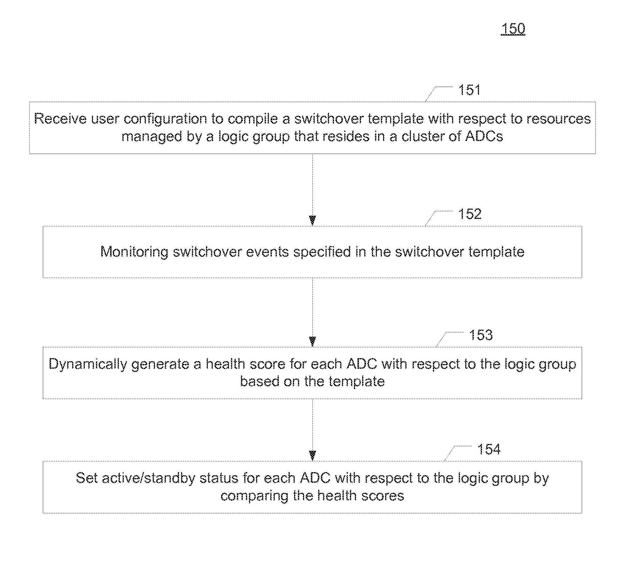
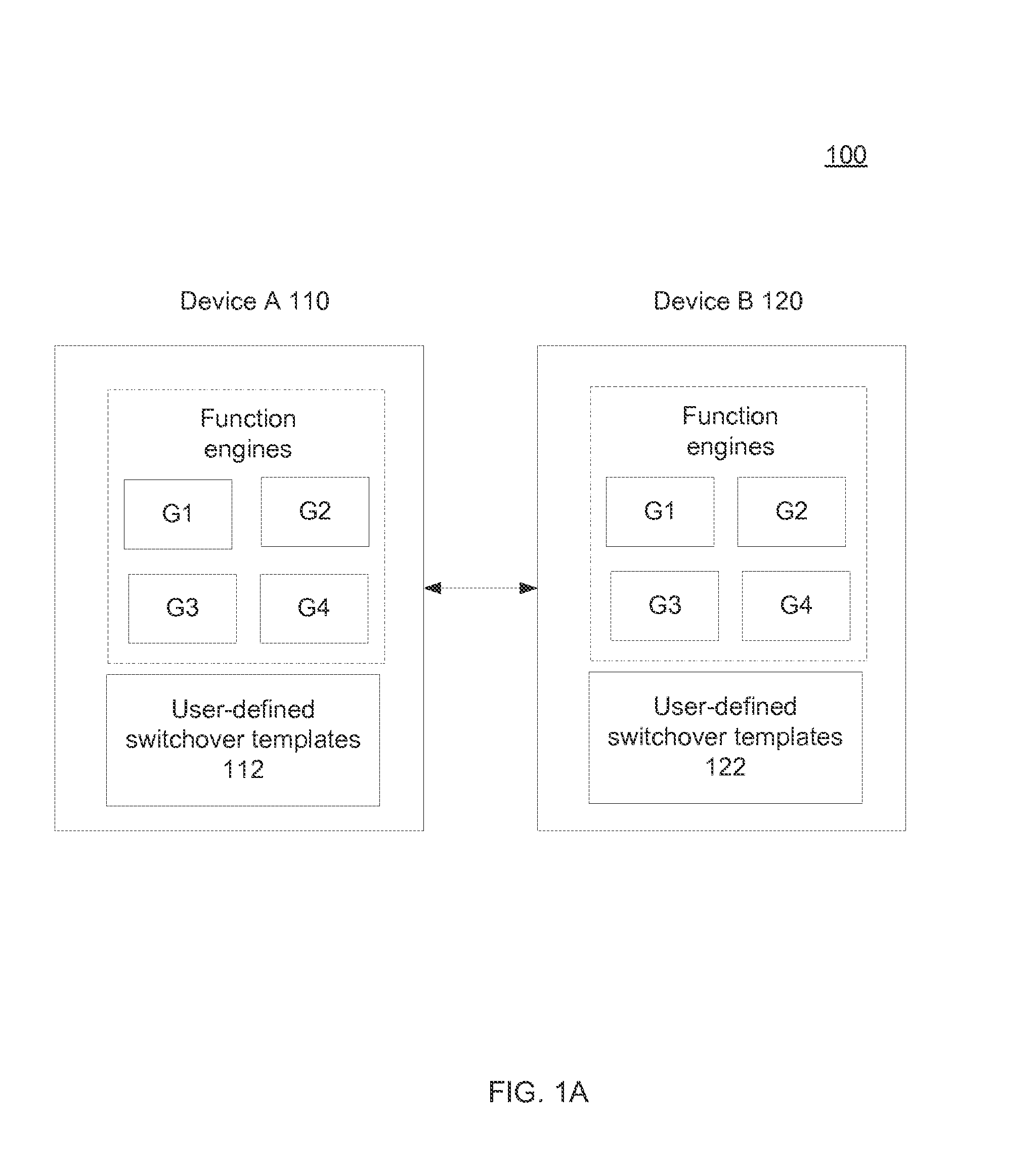
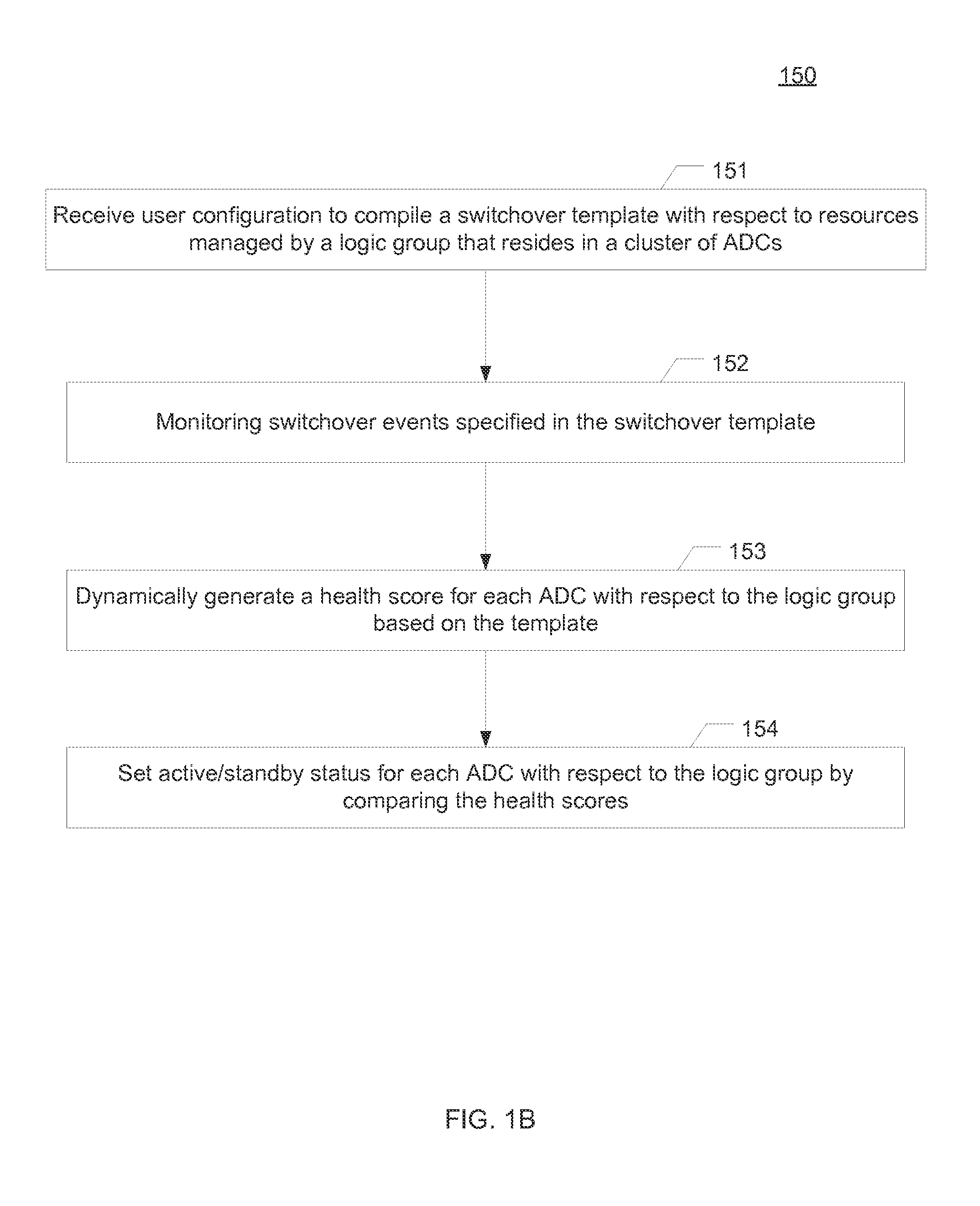
System and method of determining active / standby statuses of an intermediary device with respect to a logic group based on a user defined switchover policy. A user is allowed to configure a template to determine respective health levels for multiple sets of delivery resources. Each set of resources associated with a function engine residing in a respective intermediary device. The multiple sets of resources, in conjunction with the associated function engines, are equivalently operable to provide the same service function. The template may include user-specified events and respective weight factors. The specified events are monitored and a health score is dynamically derived for each delivery resource based on the template. Based on an updated health score rank with respect to the service function, a switchover may automatically occur from an intermediary device of a lower health score to another device with a higher health score.

Description

TECHNICAL FIELD[0001]The present disclosure relates generally to the field of communication networks and severs, and, more specifically, to the field of redundancy management in communication networks and servers.BACKGROUND[0002]A business entity that provides Internet services (e.g., a search engine, a data center, etc.) through a server-client network usually deploys intermediary devices between the servers and client devices to manage and control the network traffic to enhance the client-user experience. These intermediary devices may be an application delivery controller, a wide area network optimizer controller, a gateway, a service control engine, etc., or any other application optimization tools. Such an intermediary devices may be configured to perform a wide range of functionalities for purposes of application optimization and acceleration, such as load balancing (e.g., for layer 2, layer 4, or layer 7 services), caching, quality of service (QoS) processes, traffic steering...

Claims


Application Information

Patent Timeline
IPC IPC(8): H04L12/24H04L12/713H04L12/26H04L45/28H04L45/586
CPCH04L41/0663H04L43/0817H04L45/586H04L45/28H04L63/0272H04L43/0876H04L41/0668H04L41/5096H04L43/0823
Inventor WANG, MIAOWANG, XIN
Owner A10 NETWORKS
Learn More