Method and system for network-assisted interference suppression/cancelation

a technology of interference suppression and network assistance, applied in the field of radio communication system, can solve the problems of performance degradation, strong interference, and significant degradation of user throughput, and achieve the effect of effective interference suppression/cancellation

Inactive Publication Date: 2015-12-31
NEC CORP
View PDF5 Cites 26 Cited by
  • Summary
  • Abstract
  • Description
  • Claims
  • Application Information

AI Technical Summary

Benefits of technology

[0030]According to the present invention, effective interference suppression / cancelation at a user equipment can be made in downlink coordinated multi-point (CoMP) transmission.
[0031]For a more complete understanding of the present disclosure and its advantages, reference is now made to the following description taken in conjunction with the accompanying drawings, in which like reference numerals represent like parts:

Problems solved by technology

As illustrated in FIG. 3, the dense small cell scenarios in Heterogeneous Network (HetNet) are considered with large number of low power nodes (LPNs) and / or smaller inter-point distance in LTE Rel. 12. As the number of LPNs increases, the inter-point interference becomes significant, resulting in performance degradation.
However, as illustrated in FIG. 4, strong precoded interferences from the following two types of points may result in significant degradation of user throughput:Type—1: A point in the CMS, which is not selected as a TP or a CS / CB point, may dynamically result in strong interference to a CoMP UE, e.g., Point 2 in the CMS of Points 0, 1 and 2 in FIG. 4; andType—2: A point outside the CMS, which has high RSRP, may dynamically result in strong interference to a CoMP UE, e.g., Point 3 outside the CMS of Points 0, 1 and 2 in FIG. 4.
At this moment, Point 2 in the CMS is not selected (type—1 point) and therefore, the transmission of the other UE's data at Point 2 may result in the strong interference to the target UE0.

Method used


Image

  • Method and system for network-assisted interference suppression/cancelation
  • Method and system for network-assisted interference suppression/cancelation
  • Method and system for network-assisted interference suppression/cancelation

Examples


first example

1. FIRST EXAMPLE

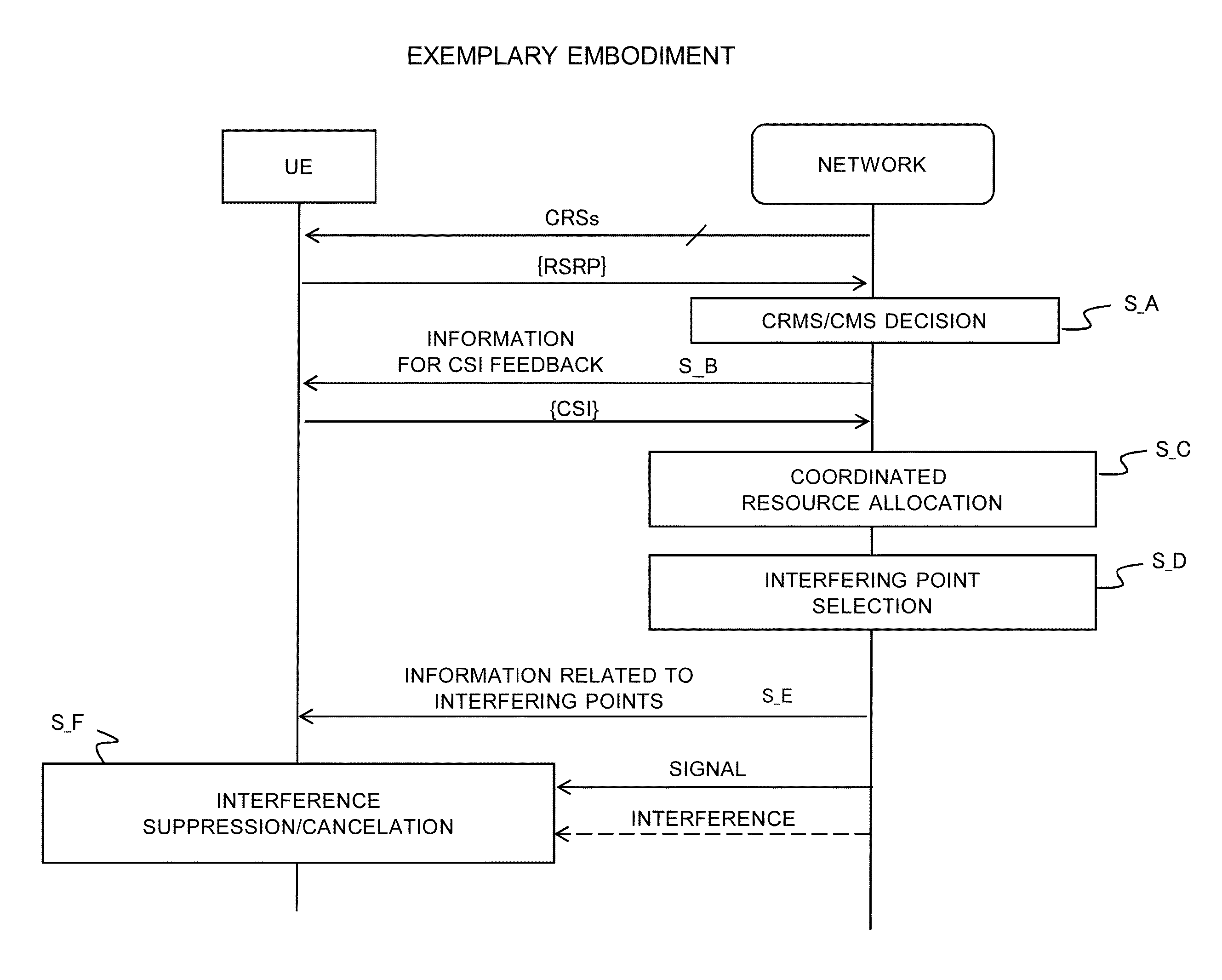
[0055]A first example of the exemplary embodiment is used to suppress interference from a point inside or outside the CMS. A system according to the first example is shown in FIGS. 8 and 9. An operation of the present example is illustrated in FIG. 10.

1.1) System Structure

[0056]As illustrated in FIG. 8, a centralized scheduler 100 is located in Macro eNB 10 to control all the LPNs, LPN0-LPNn, which are connected to the Macro eNB 10 through respective backhaul link (BL). The centralized scheduler 100 includes a CRMS and CMS decision section 101, a RS configuration section 102, a resource allocation section 103, a PQL configuration section 104, a IS configuration section 105, and a controller 106. The CRMS and CMS decision section 101 is in charge of deciding on which point is included in the CRMS and CMS respectively based on the UE reported RSRP. In RS configuration section 102, the CSI-RS and DM-RS are respectively configured for the channel estimation and data demo...

second example

2. SECOND EXAMPLE

[0084]A second example of the exemplary embodiment is used to cancel interference from a point inside or outside the CMS. A system according to the second example is shown in FIGS. 13 and 14. An operation of the present example is illustrated in FIG. 10.

2.1) System Structure

[0085]Referring to FIG. 13, the system structure of the second example is basically identical to that of the first example as shown in FIG. 8 except that the Macro eNB 10 is provided with an IC configuration section 120 replacing the IS configuration section 105 of the first example and the UE 30 is provided with an advanced receiver 323 which has an IC function replacing the advanced receiver 303, an interfering channel measurement section 324 replacing the interfering channel measurement section 304 and an interfering data replica generation section 325. Accordingly, other blocks similar to those previously described with reference to FIG. 8 are denoted by the same reference numerals and detail...


PUM


Abstract

A system which can achieve effective interference suppression/cancelation in downlink coordinated multi-point (CpMP) transmission is provided. The system has a network including multiple points which are capable of communicating with a user equipment, wherein the network sends information related to an interfering point to the user equipment for interference suppression or cancelation at the user equipment, wherein the interfering point is a candidate for a coordinated multi-point measurement set of the user equipment but not selected for any coordinated multi-point scheme.

Description

TECHNICAL FIELD [0001]The present invention relates generally to a radio communication system and, more specifically, to techniques of interference suppression / cancellation in downlink coordinated multi-point (CoMP) transmission.BACKGROUND ART [0002]Coordinated multi-point transmission / reception is considered in LTE (Long Term Evolution)-Advanced Release 11(Rel. 11) as a tool to improve the coverage of high data rates, the cell-edge throughput, and also to increase the system throughput as described in the Sect. 4 of NPL1.[0003]The CoMP schemes, joint transmission (JT), dynamic point selection (DPS), and coordinated scheduling / coordinated beamforming (CS / CB) have been agreed to be supported as described in the Sect. 5.1.3 of NPL1. For JT, multiple transmission points (TPs) are selected for simultaneous data transmission and the interference comes from the points other than the selected TPs. For DPS, only one TP is dynamically selected and the interference comes from the points other...

Claims


Application Information

Patent Timeline
Patent Type & Authority Applications(United States)
IPC IPC(8): H04W72/12H04L5/00H04B7/06H04W74/00H04B7/02
CPCH04B17/354H04B7/024H04L5/0091H04L5/0035H04J11/0053H04B7/0626H04L5/0048H04W72/1231H04W74/006H04W72/542
Inventor LIU, LEISHII, NAOTOKAKURA, YOSHIKAZU
Owner NEC CORP
Why Eureka
Try Eureka