
Composite Metal and Bone Orthopedic Fixation Devices

a technology of orthopedic fixation devices and metals, applied in the direction of osteosynthesis devices, ligaments, prostheses, etc., can solve the problems of inability to fully integrate the metallic the interface between the metallic device and the surrounding bone is relatively non-flexible and unyielding, and the fracture of the bone remains a devastating problem, etc., to facilitate the healing of fractured bones and enhance the bio-integration of the device with the surrounding bone tissue

Inactive Publication Date: 2016-01-07
STC UNM
View PDF30 Cites 24 Cited by
  • Summary
  • Abstract
  • Description
  • Claims
  • Application Information

AI Technical Summary

Benefits of technology

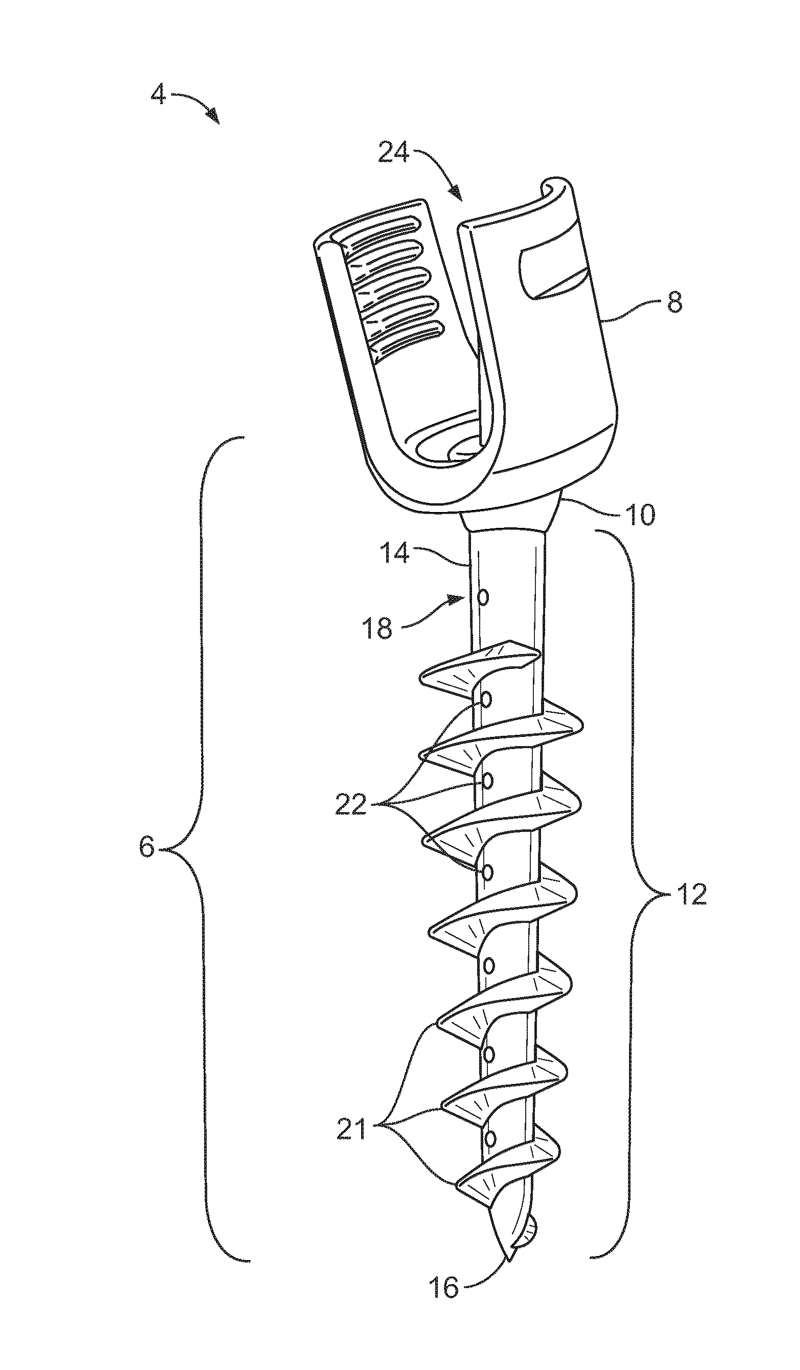
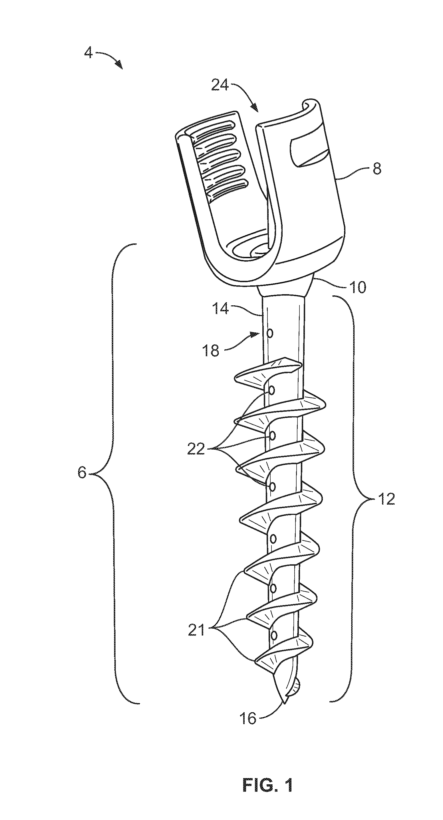
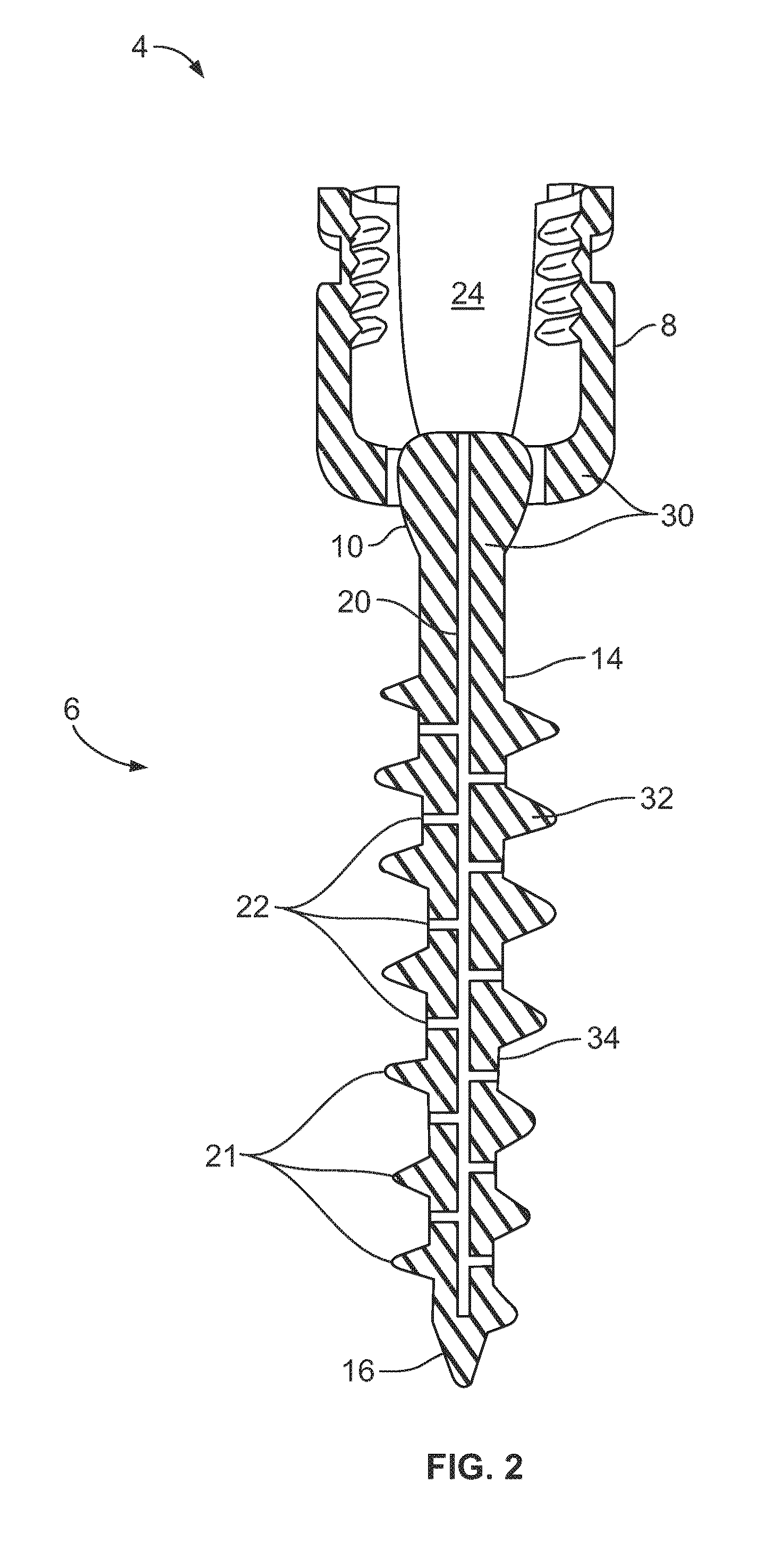
[0017]Accordingly, the inventor herein discloses innovative orthopedic fixation devices and methods, such as pedicle screws, rods, plates, set-screws, spinal interbody spacers, and cages, to facilitate healing of fractured bones and for spine stabilization. The innovative devices are made of composite materials comprising both bone and metal, in a variety of compositions and geometric configurations; that are designed to provide both the necessary strength and load-carrying capabilities, along with means and methods for enhanced bio-integration of the devices with the surrounding bone tissue.
[0035]Each of the above constructs presented may also be implanted with a radiofrequency stimulation capability. This will enable placement of external source of stimulation to the implanted radiofrequency implant allowing for increased fusion to occur.
[0042]In one example, the method can comprise: (1) providing a central reservoir (e.g., a cannulated portion) comprising a supply of precursor bone material (i.e., a “bone cocktail”) comprising a mixture of stem cells, small particles of allograft and / or autograft bone, and (optionally) bone growth factors, such as BMP-2; then (2) migrating said mixture through fenestrations that are fluidically-connected to the central reservoir at one end of the fenestration and to the outer surface of the device at the other end of the fenestration; (3) migrating / flowing said bone precursor mixture onto the exterior surface of the device; and, finally, (4) transforming, over time, the bone precursor mixture into a continuous, consolidated layer of solid, living bone tissue that has the capability to infiltrate and bond to a patient's pre-existing bone structure, thereby enhancing bio-integration of the orthopedic device or implant.

Problems solved by technology

However, there are many complications associated with placement of screws within the lumbar and thoracic spine, as well as the entire spinal axis.
Infection continues to be a devastating problem post-operatively in patients with spinal instrumentation and fusion.
However, due to the irregularity of bone anatomy, it was unlikely that once the screws had been implanted into the spine pedicles that the transverse holes in their heads would be properly aligned for rod insertion.
While the use of such rigid materials provides sufficient strength and load-carrying capabilities to avoid fractures or breakage, the interface between the metallic device and the surrounding bone is relatively non-flexible and unyielding.
While bone is quite strong in compressive loading, it is relatively weak in tension and shear.

Method used


Image

  • Composite Metal and Bone Orthopedic Fixation Devices
  • Composite Metal and Bone Orthopedic Fixation Devices
  • Composite Metal and Bone Orthopedic Fixation Devices

Examples


Embodiment Construction

Abbreviations and Definitions

[0065]To facilitate understanding of the invention, a number of terms and abbreviations as used herein are defined below as follows:

[0066]When introducing elements of the present invention or the preferred embodiment(s) thereof, the articles “a”, “an”, “the” and “said” are intended to mean that there are one or more of the elements. The terms “comprising”, “including” and “having” are intended to be inclusive and mean that there may be additional elements other than the listed elements.

[0067]The term “and / or” when used in a list of two or more items, means that any one of the listed items can be employed by itself or in combination with any one or more of the listed items. For example, the expression “A and / or B” is intended to mean either or both of A and B, i.e. A alone, B alone, or A and B in combination. The expression “A, B and / or C” is intended to mean: A alone, B alone, C alone, A and B in combination, A and C in combination, B and C in combinatio...


PUM

PropertyMeasurementUnit
pullout forceaaaaaaaaaa
widthaaaaaaaaaa
thickaaaaaaaaaa

Abstract

Composite orthopedic devices that facilitate spine stabilization, such as: bone screws, rods, plates, interbodies, and corpectomy cages are disclosed. They are designed to provide both strength and load carrying capabilities, while increasing bio-integration of the devices with the surrounding bone tissue. They are constructed of composite layers of allograft and / or autograft bone and a structural material, such as titanium alloy or carbon / graphite fiber composite. Cannulations within the device are loaded with a mixture of stem cells, particles of allograft and / or autograft bone, and bone growth factors, such as BMP-2. The cannulations are connected to the surface of the device via multiple fenestrations that provide pathways to supply the bone / stem cell mixture to the surface, allowing living bone tissue to grow and insure bio-integration. The devices can also have radiofrequency (RF) stimulation implantation within the structure of the implanted device, capable of responding to external RF stimulation of enhanced bone growth.

Description

CROSS-REFERENCE TO RELATED APPLICATIONS[0001]This application claims the benefit of US Provisional Patent Application by Paul E. Kaloostian, Ser. No. 61 / 660,133, “Device for Guiding and / or Forming a Hole in Bone Tissue and Methods of Use”, filed Jun. 15, 2012; and also US Provisional Patent Application by Paul E. Kaloostian, Ser. No. 61 / 660,107, “Orthopedic Devices and Methods of Use”, filed Jun. 15, 2012; both of which are incorporated herein by reference.STATEMENT REGARDING FEDERALLY SPONSORED RESEARCH OR DEVELOPMENT[0002]Not Applicable.THE NAMES OF THE PARTIES TO A JOINT RESEARCH AGREEMENT[0003]Not Applicable.INCORPORATION-BY-REFERENCE OF MATERIAL SUBMITTED ON A COMPACT DISC[0004]Not Applicable.BACKGROUND OF THE INVENTION[0005]1. Field of the Invention[0006]The present invention relates generally to orthopedic fixation devices, fasteners, and implants that are used in orthopedic surgery, neurosurgery, plastic surgery, hand surgery, foot and ankle surgery, and Ear-Nose-Throat (ENT...

Claims


Application Information

Patent Timeline
Patent Type & Authority Applications(United States)
IPC IPC(8): A61B17/86A61B17/70
CPCA61B17/864A61B17/8625A61B17/866A61B17/7035A61B17/8615A61B17/7002A61B17/8685A61B17/702A61B17/7037A61B17/7098A61B17/80A61B17/8841A61F2/44A61F2002/2835A61F2002/30405A61F2002/3055A61F2002/30601A61F2002/30784A61F2002/30787A61F2310/00023A61F2310/00359A61F2310/00958A61F2310/0097A61B17/68A61B17/8605A61B2017/00933A61B2017/00964
Inventor KALOOSTIAN, PAUL, E.
Owner STC UNM
Learn More