Eureka AIR delivers breakthrough ideas for toughest innovation challenges, trusted by R&D personnel around the world.

Liquid nebulization systems and methods

a liquid nebulization system and liquid nebulization technology, applied in the direction of inhalators, medical devices, other medical devices, etc., can solve the problems of medicament contamination by users or other sources, medicament contamination is particularly problematic, and the force of aerosolized medicament is often too great or too little for substantially all the metered doses

Active Publication Date: 2016-01-07
AERAMI THERAPEUTICS INC
View PDF12 Cites 39 Cited by
  • Summary
  • Abstract
  • Description
  • Claims
  • Application Information

AI Technical Summary

Benefits of technology

The patent provides an aerosolization device for delivering medicament to users. The device includes a conduit, an aerosol generator, a fluid receiving chamber, a restrictor, and an indicator mechanism. The conduit has an inner wall and a mouthpiece end, and the aerosol generator includes a vibratable mesh that is in communication with the conduit. The device is designed to aerosolize the liquid medicament only when certain flow parameters are within a desired range. The technical effect of this invention is to provide a more effective and precise delivery of aerosolized medicament to users' respiratory system.

Problems solved by technology

Current aerosolization systems often provide inconsistent doses by having some of the medicament remain in a reservoir in liquid form after the aerosolization process.
Additionally, the aerosolized medicament is often delivered with too great or too little force for substantially all of the metered dose to properly enter the user's respiratory system.
A further problem of current aerosolization systems is a tendency for the medicament to become contaminated by the user or other sources.
Contamination of the medicament is particularly problematic since some or all of the contaminated medicament is thereafter delivered directly to the user's respiratory system.

Method used


Image

  • Liquid nebulization systems and methods
  • Liquid nebulization systems and methods
  • Liquid nebulization systems and methods

Examples


experimental example

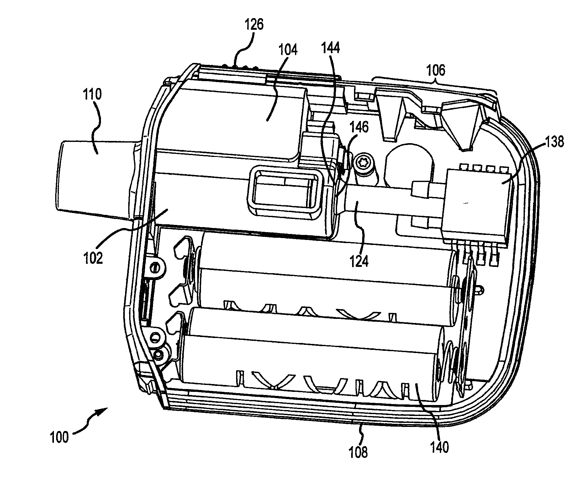
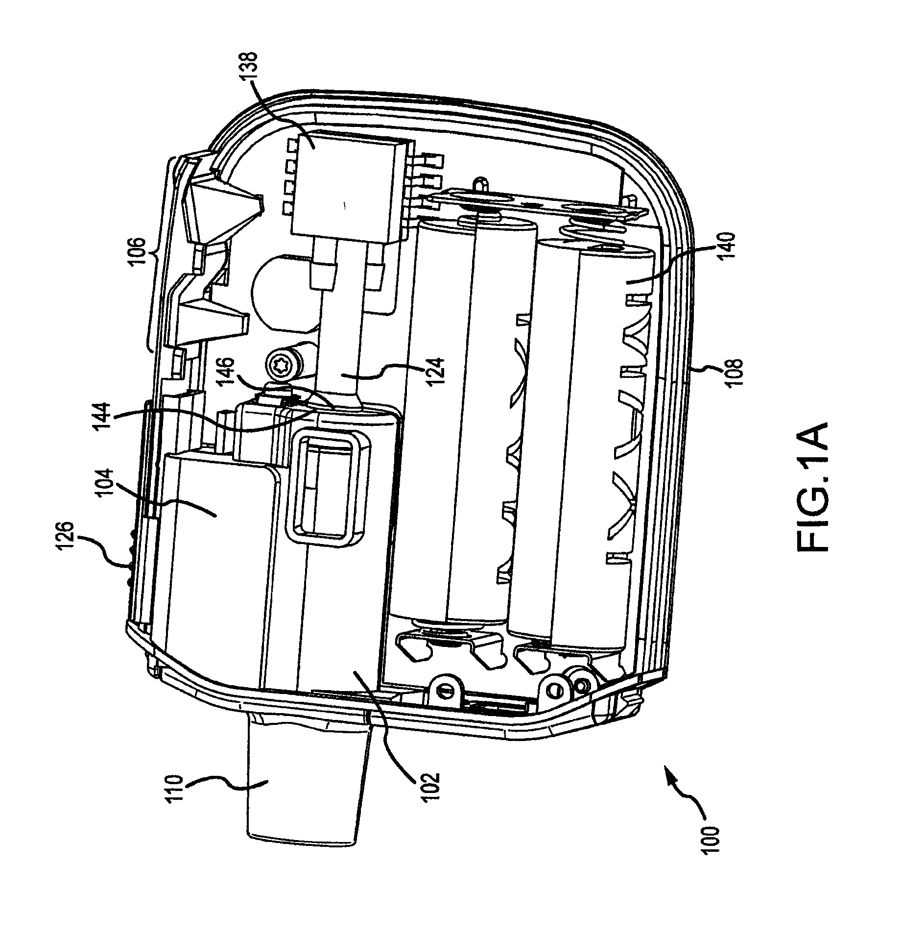
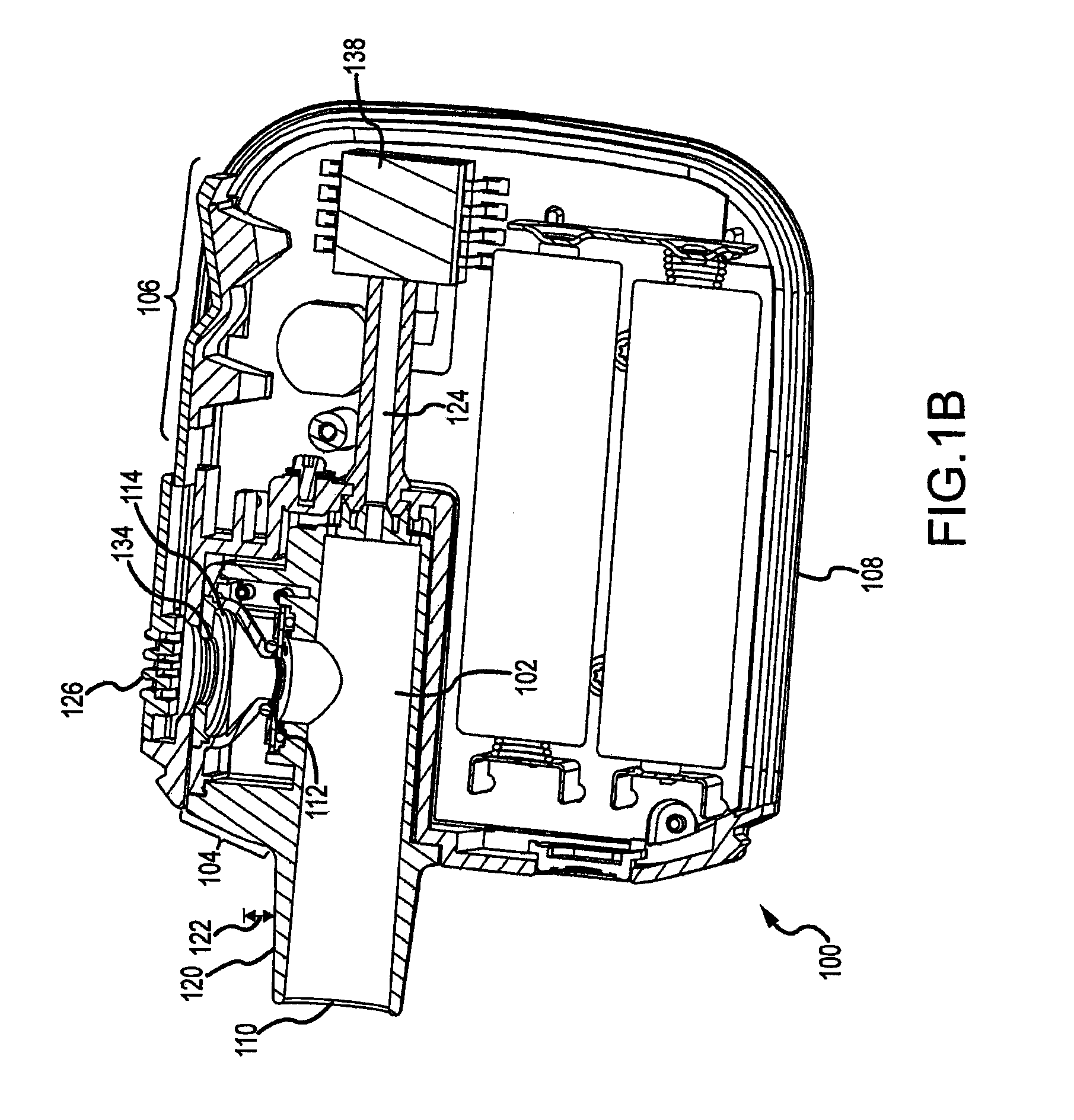
[0054]Prevention of contamination due to a user coughing or sneezing into the conduit using an aerosolization device having a vibratable mesh that is laterally offset from an inner wall of the conduit as described in FIGS. 1A and 1B, was simulated by spraying culture broth of five types of pathogens into the conduit using a 100 μl nasal spray pump. One spray was emitted from the primed nasal pump directly into an opening of the conduit. A 30 μl dose of saline was then nebulized using the aerosol generator to simulate the completion of a dose. The aerosolized saline was collected on a culture plate with medium specific to the pathogen testes. The contaminated aerosolization device was then allowed to sit in ambient conditions for 4 hours. Another dose of saline was then nebulized in the aerosolization device with the aerosolized saline again collected on a culture plate. All plates were incubated, with no pathogens found in the saline samples from either sample time.


PUM


Abstract

Embodiments provide aerosolization device for providing aerosolized medicament to user. The aerosolization device includes conduit, aerosol generator, fluid receiving chamber, restrictor within the conduit, and indicator mechanism. Conduit has an inner wall and a mouthpiece end for causing an inspiratory flow. Aerosol generator includes a vibratable mesh laterally offset from the inner wall. Fluid receiving chamber receives liquid medicament. At least a portion of chamber is tapered such that liquid medicament is directed onto vibratable mesh for aerosolization. Restrictor defines a plurality of apertures that provide increases in pressure differential that vary with inspiratory flow rate within conduit and provide relatively laminar flow downstream of restrictor. Indicator mechanism indicates a state of flow parameters relative to a predefined range. Aerosol generator is configured to aerosolize at least a portion of liquid medicament only when flow parameters of the inspiratory flow are within range.

Description

CROSS REFERENCE TO RELATED APPLICATIONS[0001]This application claims the benefit of U.S. Provisional Application No. 62 / 019,781, filed on Jul. 1, 2014, entitled “LIQUID NEBULIZATION SYSTEMS AND METHODS,” the entire disclosure of which is hereby incorporated by reference, for all purposes, as if fully set forth herein.BACKGROUND OF THE INVENTION[0002]Aerosolization systems provide effective delivery for a variety of medicaments, such as insulin and asthma medications. Such systems deliver the medicaments directly to a user's respiratory system by aerosolizing a metered dose of the medicament in liquid form. The user then inhales the aerosolized medicament directly into the respiratory system, enabling faster treatment of various medical conditions.[0003]Delivery of consistent and properly metered doses of aerosolized medicament to a user is very important. Current aerosolization systems often provide inconsistent doses by having some of the medicament remain in a reservoir in liquid ...

Claims


Application Information

Patent Timeline
IPC IPC(8): A61M15/00
CPCA61M15/0016A61M15/0005A61M15/0021A61M2206/11A61M2202/0007A61M2202/048A61M15/0068A61M11/005A61M15/0085A61M2016/0021A61M2016/0027A61M2016/003A61M2205/3331A61M2205/502A61M2205/52A61M2205/581A61M2205/582A61M2205/584A61M2205/6018A61M2205/6054A61M2205/6072A61M2205/8206A61M15/002
Inventor FINK, JIMMOLLOY, LISAMACLOUGHLIN, RONANLILLIS, CLAIRE ELIZABETHCASEY, MICHAEL JOSEPHMULLINS, JOHN MATTHEWHYLAND, KIERAN JAMESGREHAN, JOESPH MARTINSMITH, NIALL SCOTT
Owner AERAMI THERAPEUTICS INC
Why Eureka
Eureka Blog
Learn More