Telescopic cleaning system for exhaust air filters

Inactive Publication Date: 2016-01-07
ADEBA MUHENDISLIK DANISMANLIK HALKLA ILISKILER INSAAT & TICARET AS
View PDF1 Cites 17 Cited by
  • Summary
  • Abstract
  • Description
  • Claims
  • Application Information

AI Technical Summary

Benefits of technology

[0011]This invention is related with a new telescopic cleaning system on industrial air filter units covering all above mentioned needs by eliminating several disadvantages and improving the general performance of air cleaning systems.
[0012]One of the objectives of the invention is to reduce energy consumption of the system by eliminating compressed air usage necessity in filter's self-cleaning function through re utilizing the existing discharged/waste air of the system fan unit.
[0013]Another objective is to further reduce energy consumption of the system by reducing filter resistance (pressure drop) on filter units, which leads the suction fan to consume less energy to deliver required air amount for main system need. This is newlyenabled by means of a special Telescopic Cleaning Head movement in the filter unit that is applying reverse cleaning air at adequate level with balanced & well distributed manner throughout each cassette filter& media. By this function, filter media will continuously remain well cleaned leading to generate lower air passing resistance (pressure drop) and consume less energy vs. existing applic

Problems solved by technology

Existing design/system works relatively in good condition but with several weaknesses.
One of the biggest weaknesses is to consume high energy for internal filter cleaning function.
However, such air filtering units increase demands and lead the operations to invest to higher capacity systems with higher initial investment (Capital Expenditure) needs.
Efficiency of the compressed air systems (generation as well as distribution network) are relatively low due functional weaknesses of network elements with quite high pressure drops and frequently observed leakages.
Moreover, the regular operational and maintenance cost of such compressors are quite expensive due to high end technology usage inside the units.
Beside, frequent compressed air cleaning cycle of filters with low performance increases energy consumption.
Consequently, filter media may not be cleaned with full surface and leads to gradually higher resistance to the air passing through due to less available surface remains.
In other words, improperly cleaned filters generate high resistance (high pressure drop), which forces the suction fan to consume more energy to be able to generate required volume of the units serving to.
From environmental perspective, existing filtering segments are subject to heavy mechanical force of compressed air.
This leads to wears & tears as well as fatigue of the filter media.
As a result,

Method used


Image

  • Telescopic cleaning system for exhaust air filters
  • Telescopic cleaning system for exhaust air filters
  • Telescopic cleaning system for exhaust air filters

Examples


Embodiment Construction

[0058]Below explanation gives further details of mentioned telescopic cleaning system preferred structure with the objective of clear understanding of working principle with no limitation to claims.

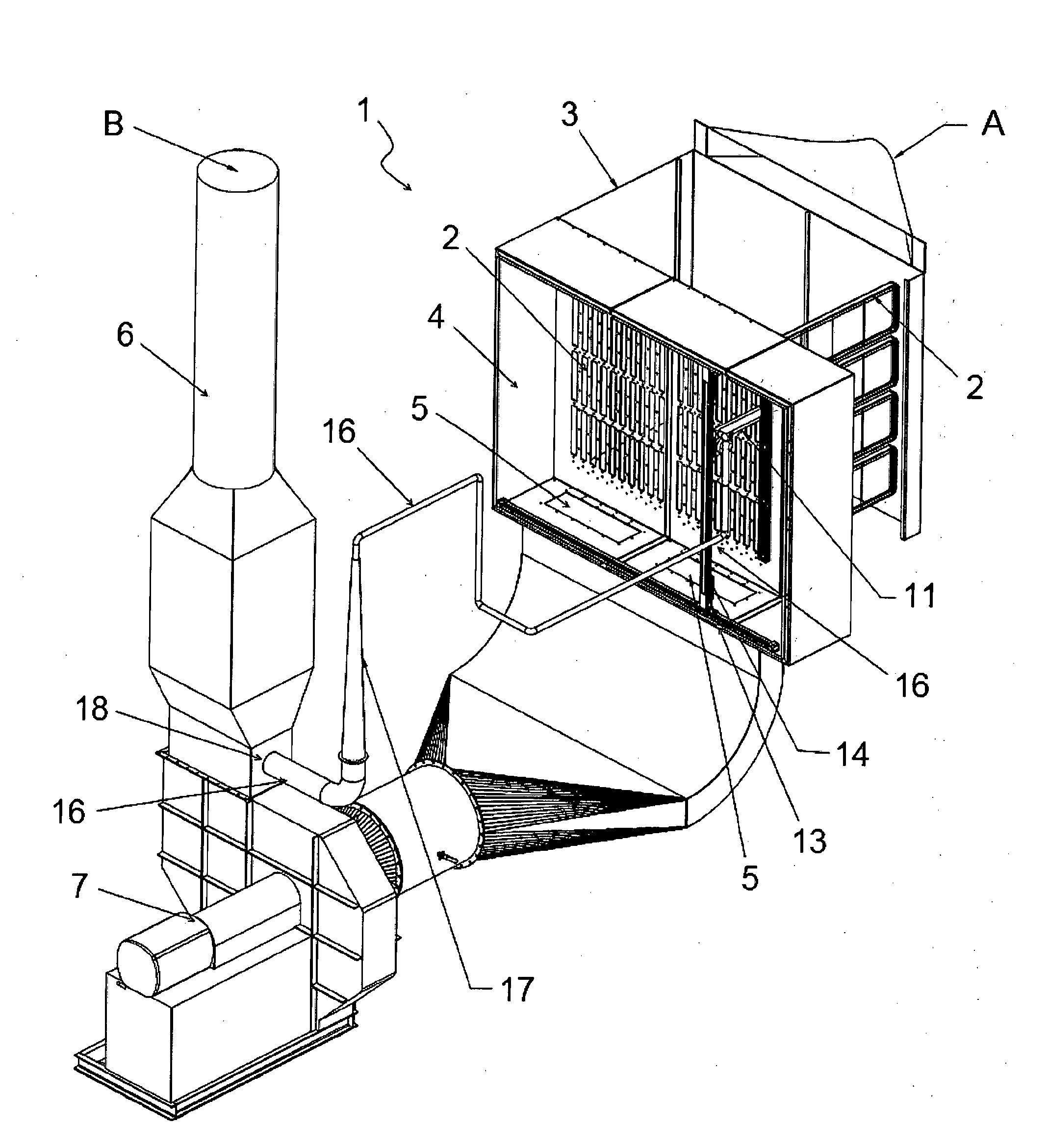
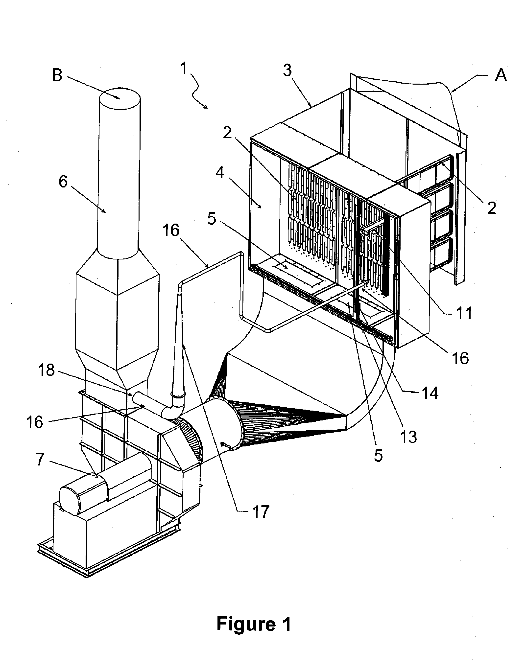
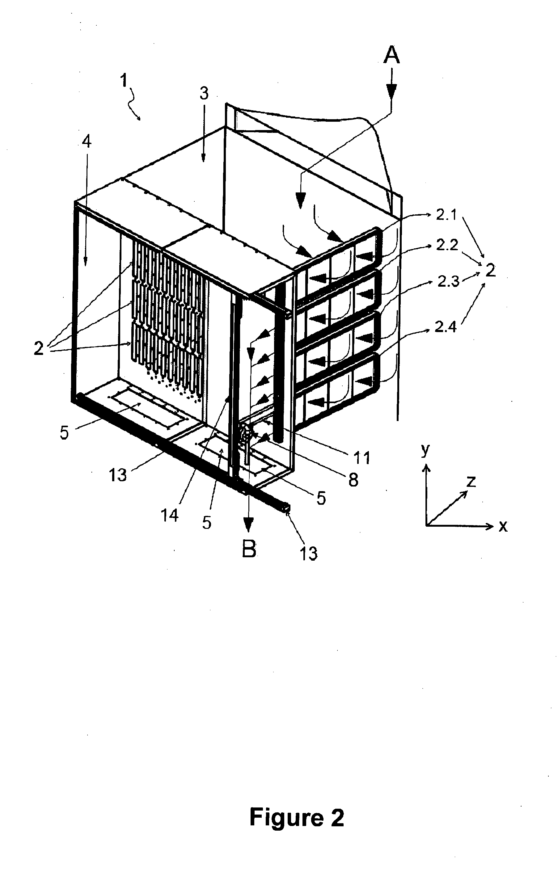
[0059]With this invention, through developed mechanical structure; a dedicated cleaning system is structured with the help of telescopic unit working over 3 dimensional moving systems, which enables to effectively clean both side of filter surfaces. In parallel, system is enabled to use the discharge / exhaust air of the suction fan as cleaning media for filters with the help of conical mechanical structure that accelerates the air under Bernoulli principle generating air jet. Filter cleaning will be achieved through a reversed air application towards to the filter surfaces from a short distance application of air jet (low pressure / high speed)

[0060]This invention involves in internal cleaning system (so called Telescopic Cleaning System (10)) of centralized extraction and filtration unit (1...


PUM


Abstract

This invention is related with the internal cleaning system (Telescopic Cleaning System (10)) of centralized extraction and filtration units (1) of industrial exhaust gases aiming to reduce overall energy consumption of such system by; avoiding the usage of compressed air being replaced with available exhaust air of the system, accelerated and applied thoroughly all surfaces of the cassette filters (2) by the help of Telescopic Cleaning System (10) and delivering efficiently cleaned filters, generating less resistance over the filter unit (1) versus comparable existing designs by the help of such efficiently cleaned filters, leading to less energy consumption on exhaust air fan.

Description

TECHNICAL FIELD[0001]This invention; involves in internal cleaning system of centralized extraction and filtration units of industrial exhaust gases such as product dusts or process related emission gases that are generated during related process to be extracted from operational environment and to be discharged to atmosphere within the limits of environmental regulations. Invention mainly covers a special telescopic cleaning system to be used at such extraction systems and filters, which is able to clean internal filtering materials by a cleaning head stands on a telescopic unit travelling all through the filter fabric surface. This enables the opportunity to use low pressure exhaust air coming out of the main suction fan at the system and consequently avoids the usage of compressed air, which is the current industry solution / standard worldwide. As a result, filters will be cleaned more effectively with almost no energy consumed.PRIOR ART[0002]Current technology uses Compressed Air ...

Claims


Application Information

Patent Timeline
IPC IPC(8): B01D46/00B01D46/02B01D46/44
CPCB01D46/0068B01D46/023B01D46/442B01D46/71
Inventor BAL, IK, HASAN, ENGIN
Owner ADEBA MUHENDISLIK DANISMANLIK HALKLA ILISKILER INSAAT & TICARET AS
Why Eureka
Try Eureka