Transport Device For Article Transport Boxes

a technology for transporting devices and articles, applied in the field of transport devices, can solve the problems of high cost, complicated structure, and inability to use distribution plastic containers, and achieve the effect of increasing cost and complicated structur

Inactive Publication Date: 2016-01-07
DAIFUKU CO LTD
View PDF0 Cites 23 Cited by
  • Summary
  • Abstract
  • Description
  • Claims
  • Application Information

AI Technical Summary

Benefits of technology

[0007]According to the transport device of the present invention capable of performing the storage and retrieval operations of the article transport box as above, the article transport box is gripped by the gripping columnar members angular in cross section through use of the corners of the article transport box having the greatest strength against an external pressure and being capable of ensuring the length, so that very ordinary general-purpose four-cornered article transport boxes having the parallelogram planar shape can be handled as they are as article transport boxes being the objects to be transported. Moreover, even if the gripping force is made sufficiently larger, the article transport box can be reliably and firmly gripped and transported without causing an unreasonable deformation thereto as compared to the case of gripping the sides between the corners.
[0008]Moreover, the elevating drive means and the gripping drive means causing the gripping columnar members to perform the necessary elevating movement and horizontal movement between the retracting position and the gripping position are both provided to the transporting traveling body. Therefore, the configuration is simplified and can be carried out inexpensively. Additionally, only the four vertically moving gripping columnar members are projected downward from below the transporting traveling body, and thus, the travel height of the transporting traveling body can be lowered at least by a height of the elevating body as compared to the case where the elevating body is vertically movably suspended below the transporting traveling body and a means for hoisting the article transport box is provided to this elevating body.
[0009]Further, the four gripping columnar members are made to have a length in an elevating direction sufficient to grip a plurality of stacked article transport boxes having the same planar size all together, whereby not only can all of them be stored and retrieved all at once even if stacked, but storage and retrieval operations limited to one or a plurality of article transport boxes at a given height of the stacked article transport boxes can also be performed simply and easily as shown in the embodiments described later.
[0010]It is, as a matter of course, conceivable that the four gripping columnar members (9a to 9d) are designed to vertically pass through the transporting traveling body (3) to be vertically movable. The article transport box (B) gripped by the four gripping columnar members (9a to 9d) is also designed to be vertically movable within a vertical through opening (10) provided to the transporting traveling body (3), together with the four gripping columnar members (9a to 9d), whereby a vertical space necessary below the transporting traveling body can be reduced, and the traveling level of the transporting traveling body can be lowered and the stack height of the article transport boxes handleable all at once can be increased.
[0011]A specific configuration in implementing the transport device of the present invention will be described. One of the four gripping columnar members (9a) which is positioned on one corner between two rectangular sides of a rectangular parallelogram space formed inside the four gripping columnar members (9a to 9d) is only vertically movably supported at a fixed position of the transporting traveling body (3) as a reference gripping columnar member, and the respective gripping columnar members (9b to 9d) positioned on the other three corners are vertically movably supported to three movable bases (13b to 13d) capable of horizontal movement in a direction parallel to one of two rectangular sides extending from each corner and horizontal movement in a direction parallel to the other side, and the gripping drive means (15) capable of moving the three movable bases (13b to 13d) by a given distance such that a space formed inside the three gripping columnar members (9b to 9d) after the horizontal movement and the reference gripping columnar member (9a) becomes a rectangular parallelogram can be used. According to this configuration, the transporting traveling body finally must be positioned at a position where the reference gripping columnar member is fitted to one corner of reference of the article transport box. However, one gripping columnar member serving as the reference gripping columnar member does not need to be moved horizontally, so that the configuration is simplified and can be carried out inexpensively.
[0015]Furthermore, to enhance the gripping force by the gripping columnar members (9a to 9d), the gripping faces of at least two diagonally positioned gripping columnar members of the four gripping columnar members (9a to 9d) can be composed of an anti-slip means (an air bag, an elastic material such as rubber, a pinholder structure composed of closely arranged movable pins each urged to project from the gripping faces, etc.) (11a, 99) inhibiting relative vertical slip with the article transport box (B) at the time of being pressure-contacted thereto. Further, at least two diagonally positioned gripping columnar members of the four gripping columnar members (9a to 9d) can have a lower end provided with a receiver (100) switchable between an acting position of receiving a bottom surface of the article transport box (B) and a retracting position of being away sideways from the article transport box (B).

Problems solved by technology

Thus, generally distributed plastic containers cannot be used as they are, as the objects to be transported.
Not only is the structure complicated and the cost becomes higher, but also the elevating body is provided with the drive means for operating the hook to engage and disengage positioned immediately above the hoisted and transported article transport box.
In practice, it is impossible in the configuration described in Patent Document 1 to handle a large number of stacked article transport boxes all at once.

Method used


Image

  • Transport Device For Article Transport Boxes
  • Transport Device For Article Transport Boxes
  • Transport Device For Article Transport Boxes

Examples


Embodiment Construction

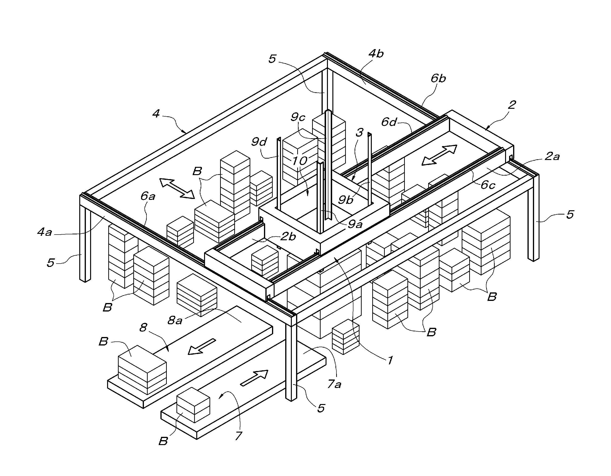
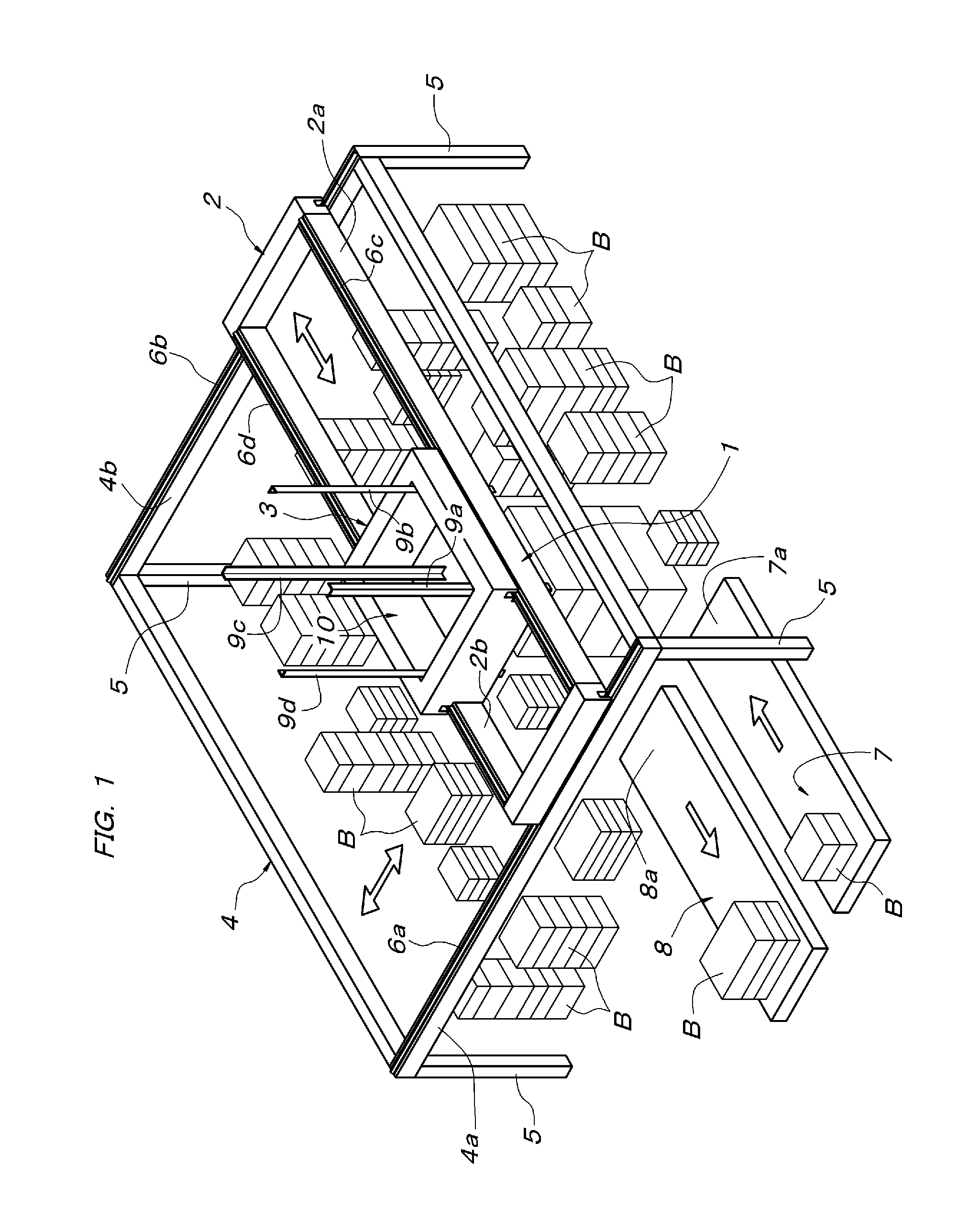
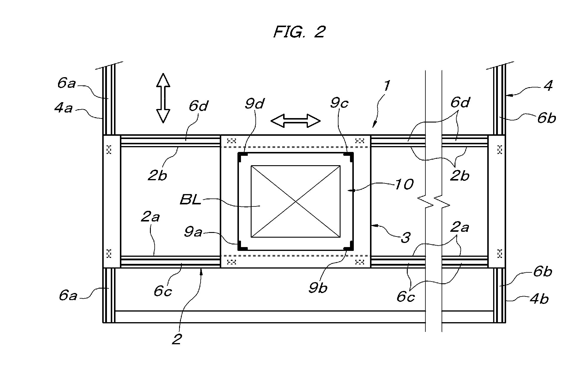
[0031]In FIG. 1 and FIG. 2, reference symbol 1 denotes an overhead traveling crane type transport device, which is arranged on an upper side of a storage area composed of a flat floor surface having a planar shape of a parallelogram. This transport device 1 is composed of a supporting traveling body 2 and a transporting traveling body 3 supported on the supporting traveling body 2 so as to be travelable in a direction perpendicular to the traveling direction of the supporting traveling body 2. In the storage area, a rectangular frame structure 4 surrounding the storage area is horizontally disposed at a fixed height above the floor surface via column members 5. The supporting traveling body 2 has both end portions supported on a pair of guide rails 6a and 6b laid on a set of mutually parallel beam members 4a and 4b of the rectangular frame structure 4, via a plurality of wheels including motor-driven drive wheels. The supporting traveling body 2 is provided with a pair of side frame...


PUM


Abstract

A transport device for article transport boxes for storing or sorting stacked box-type pallets has four vertically movable gripping columnar members on a transporting traveling body horizontally travelable on an upper side of a storage area. The gripping columnar members have an angular shape in cross section and have gripping faces pressure-contacted to both sides of each corner of an article transport box. An elevating drive means and a gripping drive means of the gripping columnar members are provided to the transporting traveling body. The gripping drive means moves at least three gripping columnar members of the four gripping columnar members horizontally between a retracting position of being away outside from each corner of the article transport box, and a gripping position of gripping the article transport box via the four corners thereof by way of the four gripping columnar members.

Description

FIELD OF THE INVENTION[0001]The present invention relates to a transport device which hoists and transports a stackable article transport box having a planar shape of a rectangular parallelogram.BACKGROUND OF THE INVENTION[0002]As this kind of transport device, there is known one in which an overhead traveling crane type transporting traveling body is provided with a vertically movably suspended elevating body, and a hook is provided below the elevating body so as to be engaged and disengaged with respect to an engaged fitting provided to the article transport box or a recessed space around the lower end thereof, as described in Patent Document 1 (Japanese unexamined patent application publication No. H06-115608).SUMMARY OF THE INVENTION[0003]In the configuration described in the above Patent Document 1, the provision of the engaged fitting exclusive for suspension to an upper end of the article transport box being an object to be transported or the formation of the article transpor...

Claims


Application Information

Patent Timeline
Patent Type & Authority Applications(United States)
IPC IPC(8): B65G63/00B65G57/03B65G59/02B66C1/10B66C1/44
CPCB65G63/004B65G57/03B66C1/44B66C1/101B65G59/02B65G1/0428B65G47/90B65G61/00B65G1/0464
Inventor TAKAO, SUZUSHI
Owner DAIFUKU CO LTD
Why Eureka
Try Eureka