Subsea valve

Active Publication Date: 2016-01-07
AKER SOLUTIONS AS
View PDF7 Cites 3 Cited by
  • Summary
  • Abstract
  • Description
  • Claims
  • Application Information

AI Technical Summary

Benefits of technology

[0014]the actuator unit and a driving part of the magnetic coupling are arranged in a sealed

Problems solved by technology

Longer step outs result in slower response time using hydraulic systems, as well as increased cost of hydraulic umbilicals.
Electric actuators are however somewhat less reliable than hydraulic actuators, which is solved by adding redundancy, but in the case of leakage of contaminating fluid into the actuator the control of the actuator and thereby the valve is lost.
Lost production for a period of time can be very expensive, but worse, if the leakage continues into the electrical control system a severe safe

Method used


Image

  • Subsea valve
  • Subsea valve
  • Subsea valve

Examples


Example

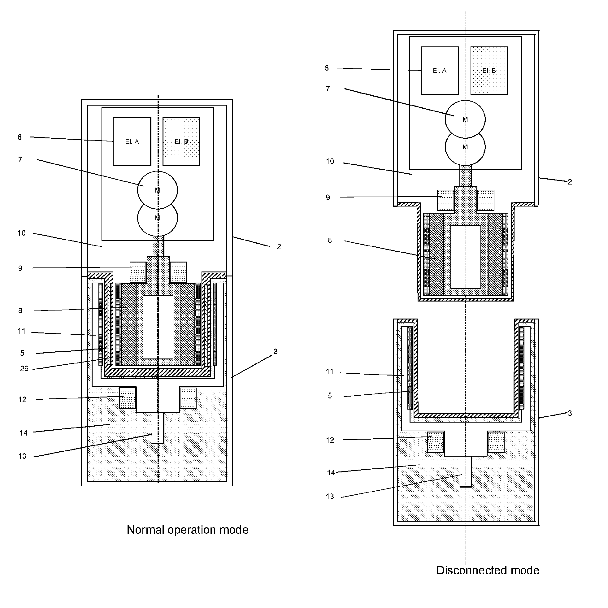
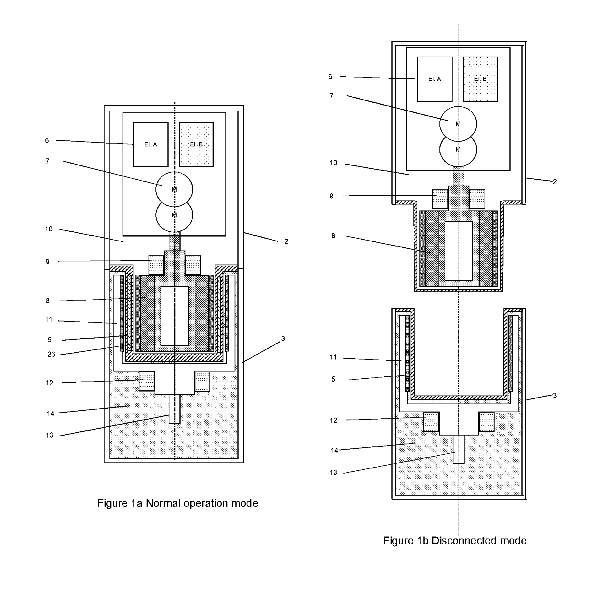
[0045]Reference is made to FIG. 1a, illustrating an embodiment of the subsea valve of the invention, in normal operation mode. More specifically, an actuator housing 2 with rotating action and magnetic transmission is illustrated, as well as a generalised and simplified valve part 3. The actuator unit 2 is isolated from the valve part 3 by a barrier wall 5, isolating the actuator from the valve part, eliminating leakage or contamination valve fluid into the actuator housing. Leakage of contained fluid into the actuator unit, which would damage said unit, is effectively eliminated. The actuator is regarded as clean, it typically contains pressure compensated hydraulic fluid 10, whilst the valve part volume is regarded as dirty, for example by containing well fluid 14 during operation. The actuator housing comprises electronic units 6, motors 7, and a high speed magnet rotor (HSMR) 8 with bearings 9. The valve part comprises inter alia a low speed magnet rotor (LSMR) 11 with bearings ...


PUM


Abstract

Subsea valve for control of fluid that can be contaminating and at elevated pressure and temperature, such as well or process fluids, the valve comprising an actuator unit and a valve part, the actuator unit can be operated in order to control the valve part, distinctive in that the actuator unit is magnetically coupled to the valve part and the coupling is through a barrier wall isolating the actuator unit from the valve part, and the actuator unit and a driving part of the magnetic coupling are arranged in a sealed actuator housing into which leakage of said contaminating fluid thereby has been eliminated.

Description

FIELD OF THE INVENTION[0001]The present invention relates to subsea valves controlled by actuators. More specifically, the invention relates to subsea valves controlled by actuators and the risk of leaking contaminating fluid that can be at high temperature and pressure, such as hydrocarbon fluid, from the valve into the valve actuator and the control system of the actuator or to the sea, which may result in loss of control of the valve or production system, a safety hazard and pollution of the sea.[0002]Relevant valves are found in subsea hydrocarbon production systems with Xmas tree production gate valves, anti surge valves, subsea process systems, manifold control valves, pressure boosting control valves, injection control valves, subsea chokes and other valves or other actuator operated units located on the seabed in the vicinity of a number of subsea wellheads and being exposed on one side for contained fluid which should not be allowed to leak into the actuator.BACKGROUND OF T...

Claims


Application Information

Patent Timeline
IPC IPC(8): E21B34/04
CPCE21B34/04F16K41/00F16K31/04E21B33/0385
Inventor STINESSEN, KJELL OLAVNYBORG, KNUT OLAFHOFFMANN, MATS
Owner AKER SOLUTIONS AS
Why Eureka
Try Eureka