Quad layer passage variable geometry turbine for turbochargers in exhaust gas recirculation engines

a turbine and variable geometry technology, applied in the direction of machines/engines, stators, electric control, etc., can solve the problems of fuel consumption penalty, fuel consumption penalty, fuel consumption loss to the engine,

Inactive Publication Date: 2016-01-07
KANGYUE TECH
View PDF5 Cites 15 Cited by
  • Summary
  • Abstract
  • Description
  • Claims
  • Application Information

AI Technical Summary

Benefits of technology

[0009]The embodiments of the present application describe a variable geometry turbine for turbochargers in exhaust gas recirculation engines which incorporates a turbine housing having an exhaust inlet with a first side receiving exhaust from cylinders having exhaust gas recirculation (EGR) and a second side receiving exhaust from non-EGR cylinders. The first side has a first EGR-driving passage and a second EGR-driving passage and the second side having a first non-EGR-driving passage and a second non-EGR-driving passage. A first control valve is associated with the second EGR-driving passage and a second control valve is associated with the second non-EGR-driving passage. A controller is adapted to control the first and second control valves.
[0010]The embodiments provide a method for exhaust recirculation control wherein exhaust is drawn from a plurality of non-EGR cylinders in an engine with a first exhaust manifo

Problems solved by technology

Unfortunately, implementation of significant amounts of EGR result in a fuel consumption (and CO2 emission) penalty.
The fuel consumption penalty is caused by the negative pressure gradient from the intake manifold to the exhaust manifold and the resulting pumping loss to the engine.
To increase the total flow through the engine, the density of t

Method used


Image

  • Quad layer passage variable geometry turbine for turbochargers in exhaust gas recirculation engines
  • Quad layer passage variable geometry turbine for turbochargers in exhaust gas recirculation engines
  • Quad layer passage variable geometry turbine for turbochargers in exhaust gas recirculation engines

Examples


Embodiment Construction

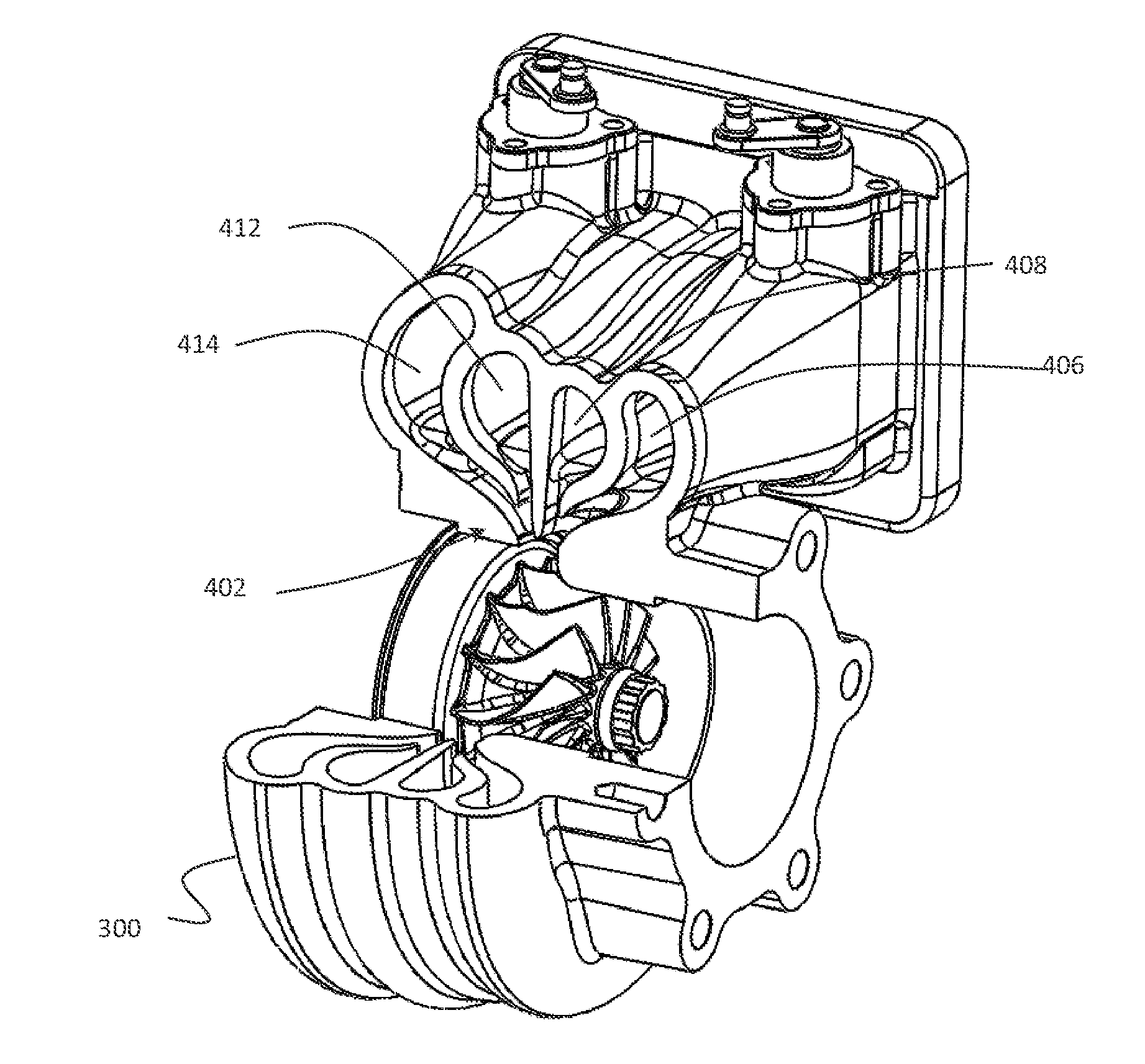
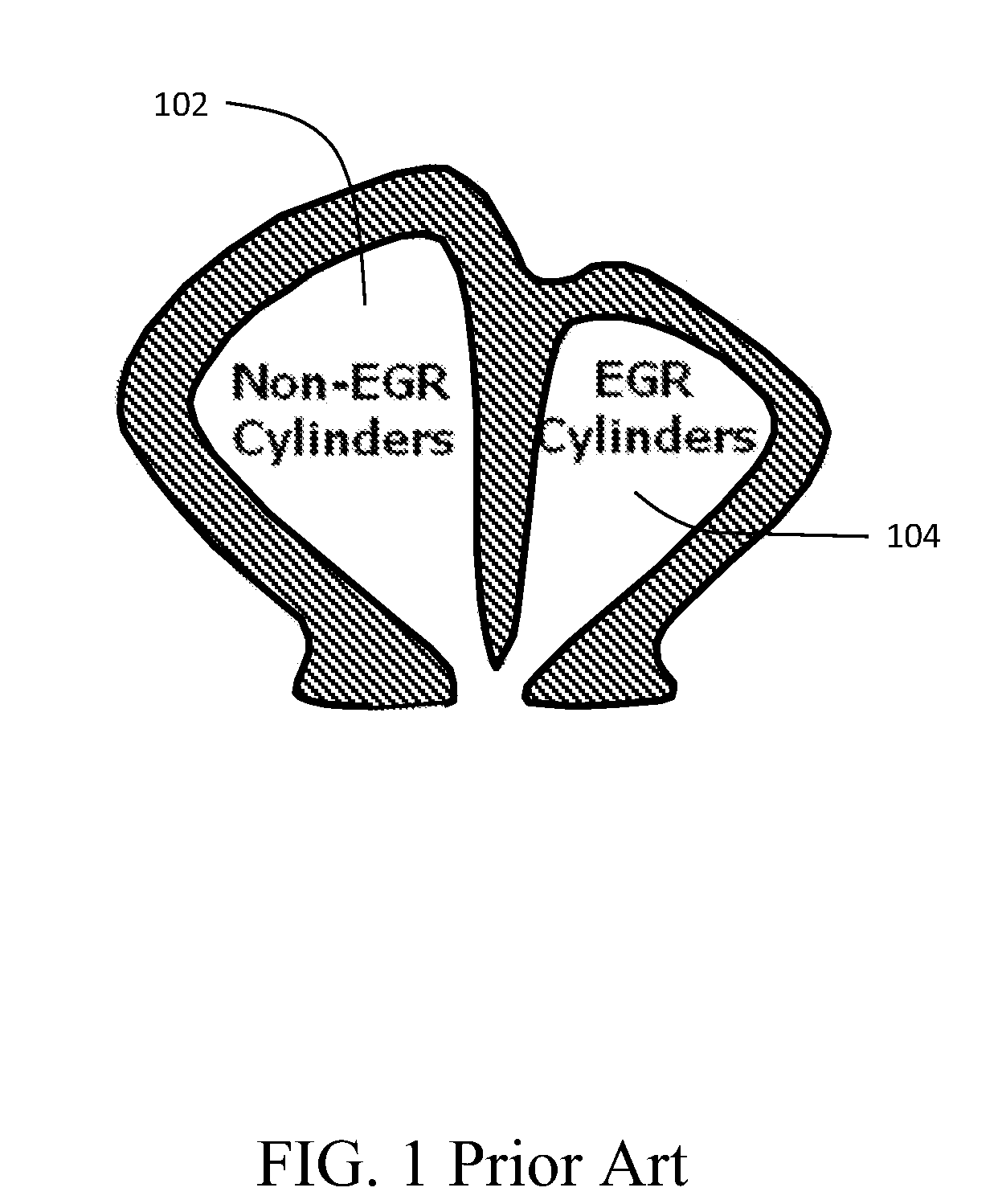
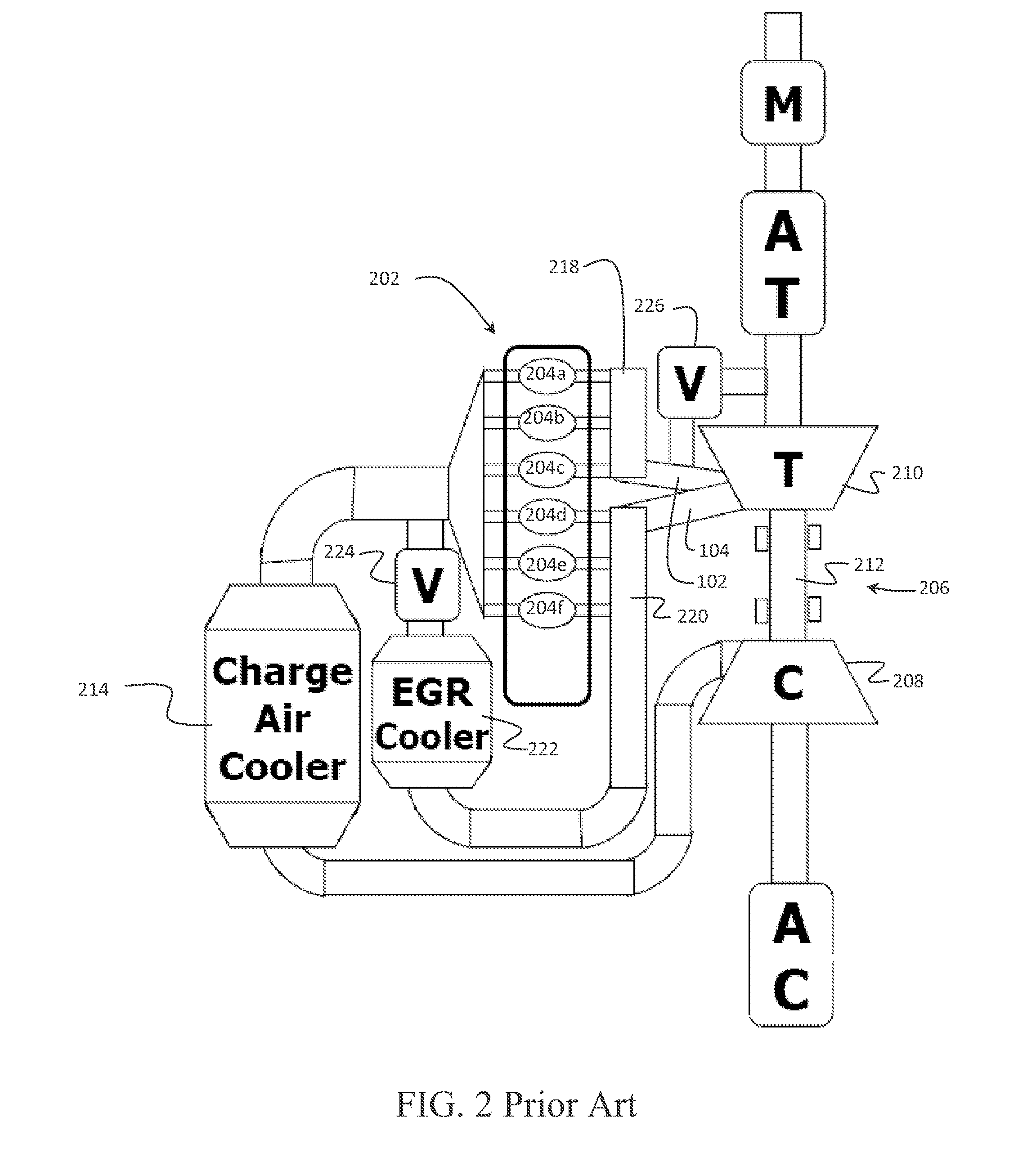
[0023]The embodiments described herein provide a low cost VGT that utilizes multiple volutes and valves to control the flow to the various volutes. The volutes are sized to provide different flow characteristics and thus provide true variable geometry turbine functionality. The embodiments receive 100% of the exhaust gases for EGR from one portion or bank of the engine's cylinders while allowing the remaining cylinders operate without the negative pressure gradient constraints necessary for EGR. For descriptive purposes, passages, volutes, or manifolds connected to the cylinders providing EGR-driving pressure differential will be defined as “EGR-driving passages”, “EGR-driving volutes” and “EGR-driving manifolds” while passages, volutes or manifolds connect to the cylinders which do not provide EGR-driving pressure differential will be defined as “non-EGR-driving passages”, “non-EGR-driving volutes” and “non-EGR-driving manifolds”. The embodiment, characterized as a Quad Layer Passa...


PUM


Abstract

A variable geometry turbine for turbochargers in exhaust gas recirculation engines incorporates a turbine housing having an exhaust inlet with a first side receiving exhaust from cylinders having exhaust gas recirculation (EGR) and a second side receiving exhaust from non-EGR cylinders. The first side has a first EGR-driving passage and a second EGR-driving passage and the second side having a first non-EGR-driving passage and a second non-EGR-driving passage. A first control valve is associated with the second EGR-driving passage and a second control valve is associated with the second non-EGR-driving passage. A controller is adapted to control the first and second control valves.

Description

BACKGROUND OF THE INVENTION[0001]1. Field of the Invention[0002]This invention relates generally to the field of charge air boosting of internal combustion engines employing exhaust gas recirculation for emissions reduction and more particularly to a variable geometry turbine employing a four passage divided volute where two paired passages provide the necessary pressure differential to drive EGR, and the other two paired passages are relieved of the EGR-driving pressure differential requirement.[0003]2. Description of the Related Art[0004]Exhaust Gas Recirculation (EGR) has been the main technology used for NOx reduction in diesel engines in countries with stringent NOx emission targets. As Selective Catalytic Reduction (SRC) technology efficiency improves, it is supplanting EGR as the prime NOx reduction technology. However, SCR requires significant and wide spread infrastructure to support replenishment of urea for SCR engines as well as sophisticated sensor and control systems f...

Claims


Application Information

Patent Timeline
IPC IPC(8): F01D17/10F02B37/02F02B37/22F02D41/00
CPCF02M25/0713F02B37/22F05D2220/40F02B37/025F01D17/105F02D41/0065F01D9/026F02B29/0437F02D41/0007F02M26/05F02M26/10F02M26/43Y02T10/12Y02T10/40
Inventor HANG, WANGARNOLD, STEVEN DONDAOJUN, YUANYANZHAO, LIWUHAI, SANG
Owner KANGYUE TECH
Why Eureka
Try Eureka