
Device to regulate the relative humidity level in a cpv module

a technology of relative humidity and solar cell, which is applied in the direction of photovoltaics, solar heat collector safety, solar radiation concentration, etc., can solve the problems of cpv module and plant approach not well adapted to large cpv modules and plants, adsorbent becomes saturated, and the need for regeneration is reduced. , to achieve the effect of prolonging the maintenance-free period

Active Publication Date: 2016-01-07
SAINT AUGUSTIN CANADA ELECTRIC
View PDF9 Cites 0 Cited by
  • Summary
  • Abstract
  • Description
  • Claims
  • Application Information

AI Technical Summary

Benefits of technology

The patent describes a way to reduce energy consumption and prevent blockages in a humidity regulation system for CPV modules. This is achieved by controlling the use of the desiccant unit and adjusting its capacity. The system can be connected in groups or individually, allowing for more efficient and precise regulation.

Problems solved by technology

In particular, an elevated level of relative humidity in the module, which can cause, under certain circumstances, condensation of water vapor on the components situated inside the module.
This approach is not well adapted to large CPV modules and plants, due to the huge dimensioning of the expansion bag.
However, with time, the adsorbent becomes saturated and must be regenerated to remove moisture.
This regeneration phase is highly energy consuming and needs an active device assuring the flow of air, in particular, a fan.
Moreover, lack of supervisory control and communication leads to an unnecessary use of the drying unit, even when the outside meteorological conditions are optimal in avoiding dry modules, in particular, elevated outside temperature and low relative humidity outside the module.

Method used


Image

  • Device to regulate the relative humidity level in a cpv module
  • Device to regulate the relative humidity level in a cpv module
  • Device to regulate the relative humidity level in a cpv module

Examples


Embodiment Construction

[0045]This disclosure will now be described with reference to specific embodiments. It will be apparent to the skilled person that features and alternatives from any of the embodiments can be combined, independently of each other, with features and alternatives of any other embodiment in accordance with the scope of the claims.

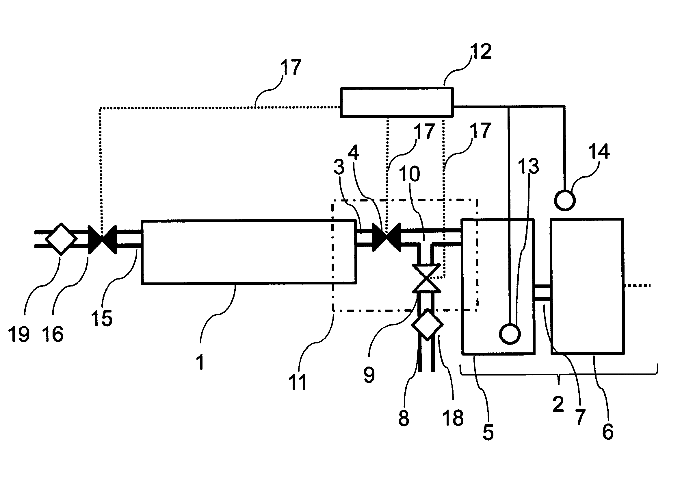
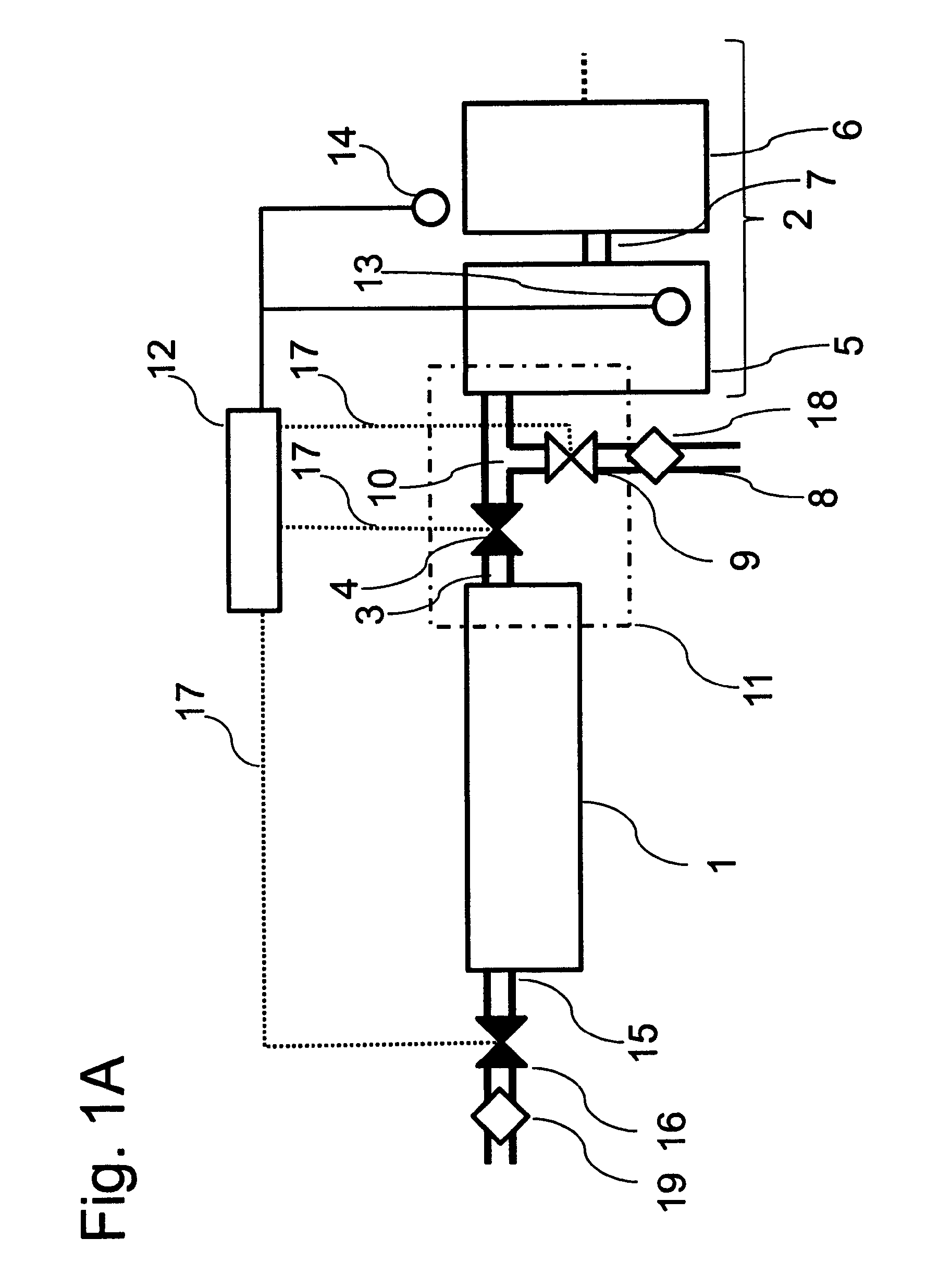
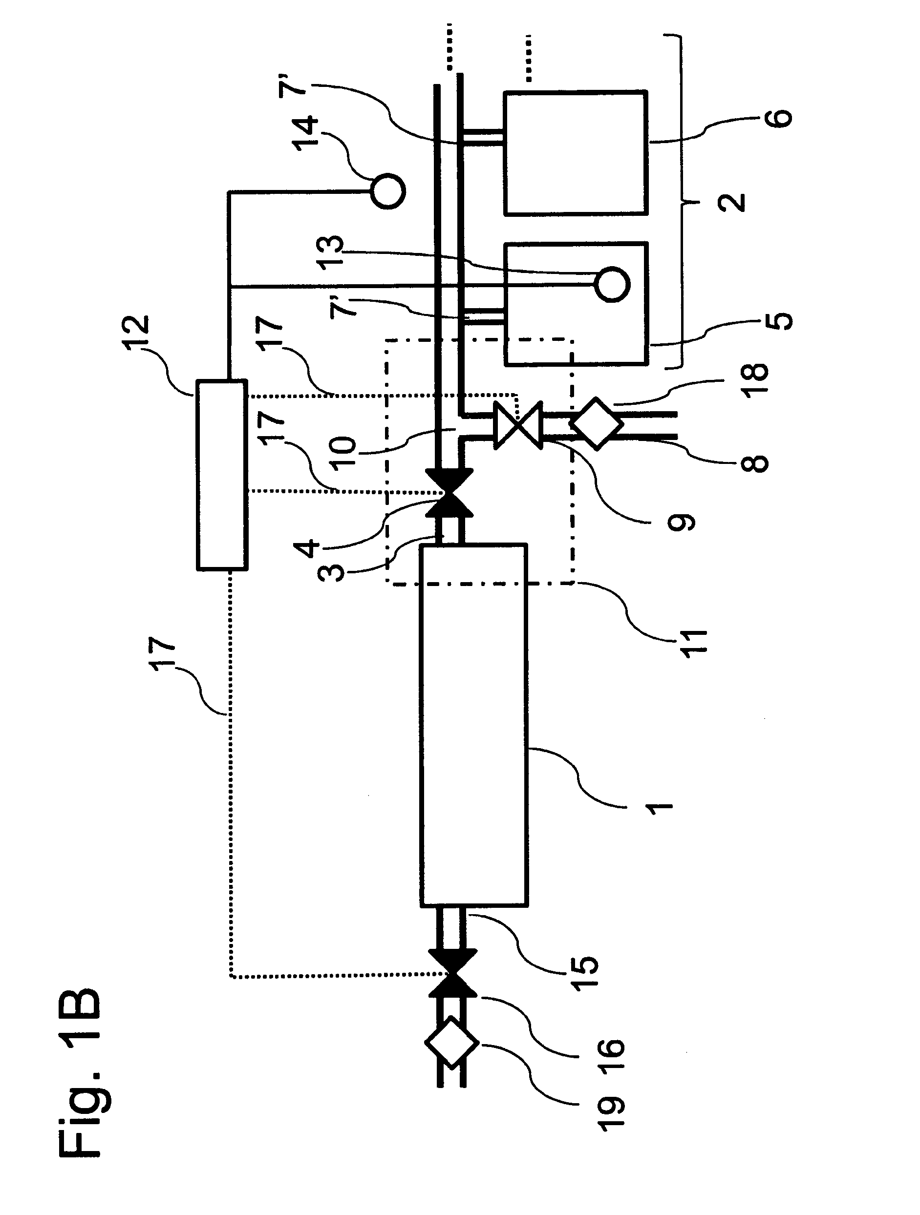
[0046]In particular, FIGS. 1A and 1B schematically illustrate a device to regulate the relative humidity level in a CPV module. The module 2 consists of at least one module unit 5. FIG. 1A schematically illustrates that module 2 comprises at least a module unit 5 and a module unit 6, which are connected in a gas-conducting manner via duct 7. FIG. 1B schematically illustrates that module 2 comprises at least a module unit 5 and a module unit 6, which are connected in a gas-conducting manner via ducts 7′. However, the disclosure is not limited thereto and further module units may be included and connected in either the way displayed in FIG. 1A and / or the way dis...


PUM


Abstract

A device to regulate the relative humidity level inside a CPV module, the device comprising a desiccant unit connected to the module via a duct, the module is also connectable to ambient atmosphere and the device comprises a switching mechanism that is actuated by a regulation unit, allowing a gas flow between the module and either the desiccant unit or ambient atmosphere. The air into the PV module is let through a dehumidifier only when there is risk of condensation, which is determined from values of the air inside and / or outside the module by sensors sensing temperature and / or relative humidity and comparing these to thresholds or to the calculated dew temperature inside the module.

Description

CROSS-REFERENCE TO RELATED APPLICATIONS [0001]This application is a national phase entry under 35 U.S.C. §371 of International Patent Application PCT / EP2014 / 000389, filed Feb. 12, 2014, designating the United States of America and published in English as International Patent Publication WO 2014 / 131492 A1 on Sep. 4, 2014, which claims the benefit under Article 8 of the Patent Cooperation Treaty and under 35 U.S.C. §119(e) to French Patent Application Serial No. 1351665, filed Feb. 26, 2013, the disclosure of each of which is hereby incorporated herein in its entirety by this reference.TECHNICAL FIELD [0002]This disclosure relates generally to a device and a method for regulating the relative humidity level inside a solar cell module. The device and the method are particularly well suited for concentrator photovoltaic (CPV) modules.BACKGROUND [0003]In CPV modules, the incident light, in particular, the solar radiation, is concentrated on a photovoltaic cell by an optical system compri...

Claims


Application Information

Patent Timeline
Patent Type & Authority Applications(United States)
IPC IPC(8): F24J2/46F24S23/00H01L31/18
CPCH01L31/18F24J2/4618H02S40/00Y02E10/40F24S40/57F24S40/42Y02E10/52Y02E10/50
Inventor GOMBERT, ANDREASSTOR, JAKOBTALIERCIO, CECILE
Owner SAINT AUGUSTIN CANADA ELECTRIC
Learn More