Oled Pixel Circuit, Driving Method of the Same, and Display Device

a technology of oled pixel circuit and driving method, applied in the field of display technology, can solve the problems of inability to meet the requirements of high-resolution large-scale display, tft threshold characteristics affecting drive current, and the inability to have completely consistent performance parameters of tfts in various oled pixel circuits

Active Publication Date: 2016-01-07
BOE TECH GRP CO LTD +1
View PDF3 Cites 21 Cited by
  • Summary
  • Abstract
  • Description
  • Claims
  • Application Information

AI Technical Summary

Benefits of technology

[0034]in the display and light-emitting step, inputting the light-emitting control signal by the second control signal line, so that the first transistor and the third transistor are turned off, the second transistor and the fourth transistor are turned on, the high level at the first voltage terminal is input to the first electrode of the second transistor, and the second electrode of the second transistor drives the light-emitting module to emit light, thereby achieving display.

Problems solved by technology

Although the PMOLED has advantages such as simple process and low cost, it cannot meet the requirements of high-resolution large-size display due to disadvantages such as crosstalk, high power consumption, short service life, and the like.
Thus, the structure of the OLED pixel circuit as shown in FIG. 1 cannot compensate drift and inconsistency of the threshold voltage of the TFT, and thus threshold characteristics of the TFT affect a drive current greatly.
Further, during manufacture of an array substrate, since the manufacturing process of an oxide TFT is not mature enough, characteristics of the oxide TFT, such as threshold voltage and mobility, varies greatly in different regions, and thus TFTs in various OLED pixel circuits cannot have completely consistent performance parameters.
At the same time, as time goes on, a threshold of each TFT will shift and a drive current of each TFT will change due to the presence of a voltage stress, resulting in that electric currents flowing through OLEDs in various OLED pixel circuits are inconsistent.
Thus, brightness of light emitted by various OLED pixel circuits is nonuniform, which affects the brightness of the final display greatly.

Method used


Image

  • Oled Pixel Circuit, Driving Method of the Same, and Display Device
  • Oled Pixel Circuit, Driving Method of the Same, and Display Device
  • Oled Pixel Circuit, Driving Method of the Same, and Display Device

Examples


Embodiment Construction

[0043]For better understanding the technical solutions of the present invention by a person skilled in the art, an OLED pixel circuit, a driving method of the same, and a display device according to the present invention will be described in detail with reference to the drawings and the following embodiments.

[0044]An OLED pixel circuit is provided according to one aspect of the present invention.

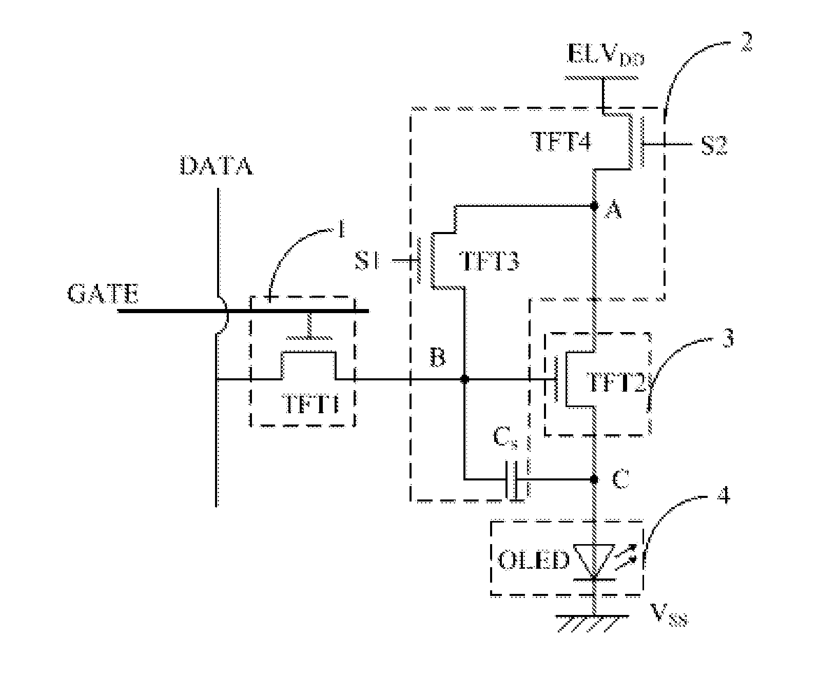
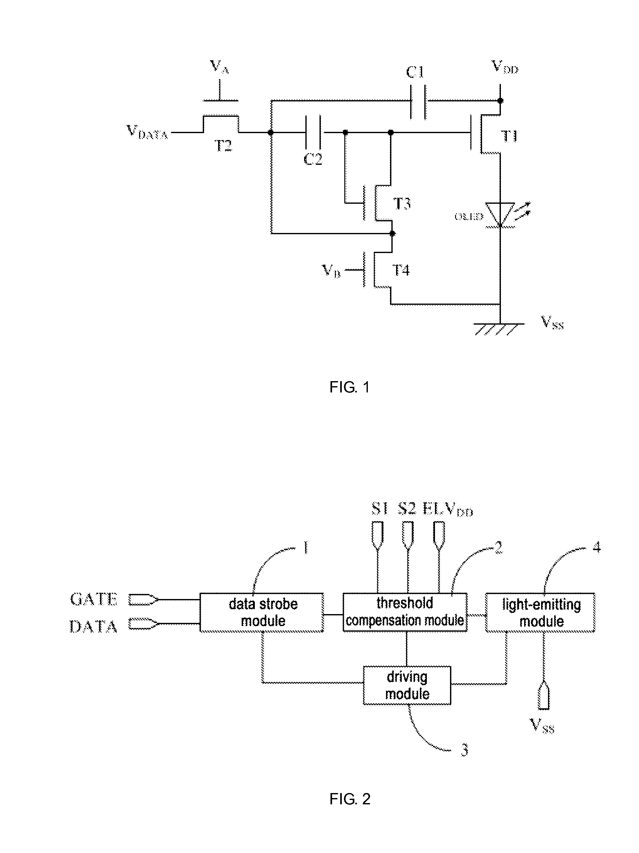
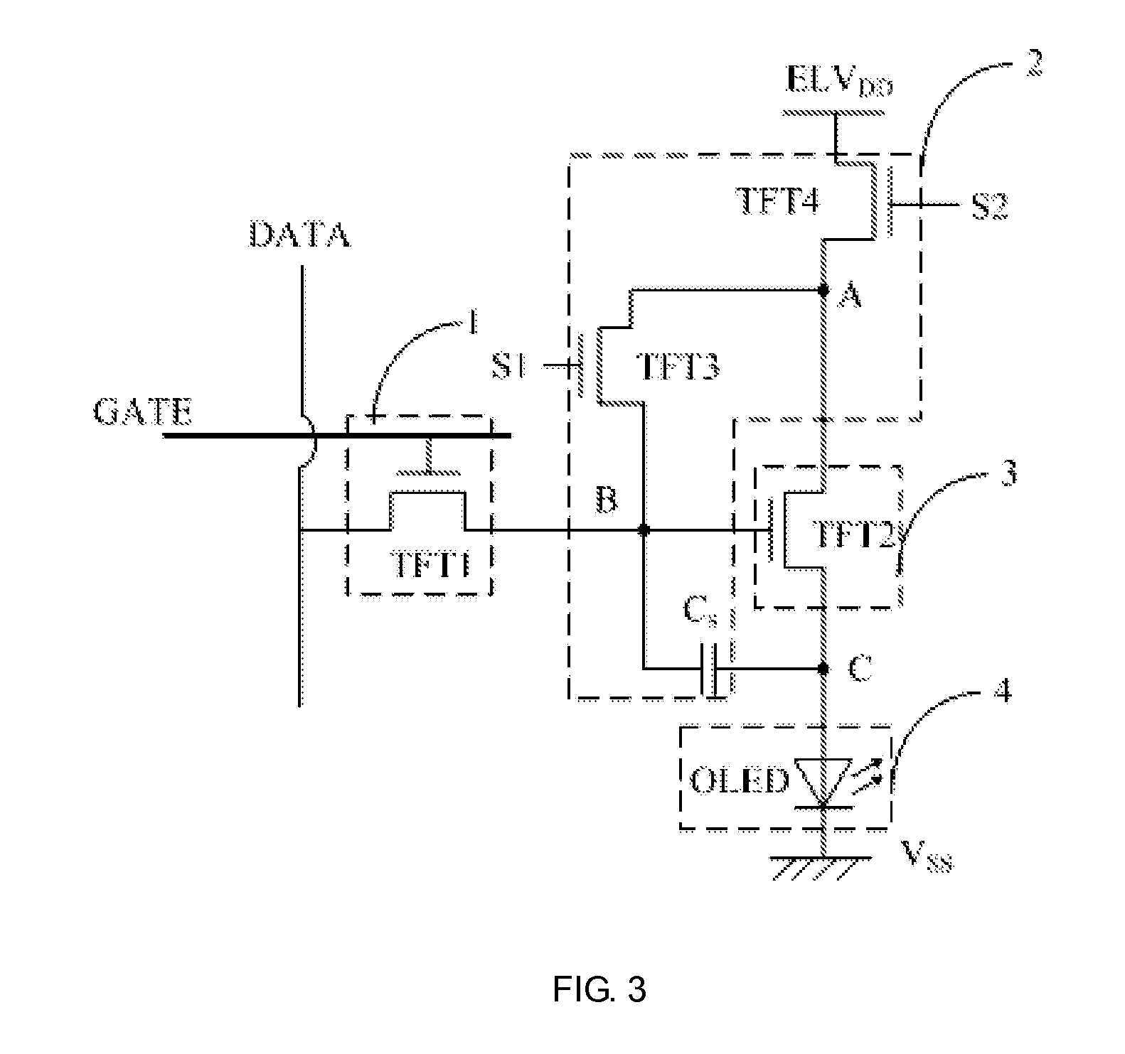
[0045]FIG. 2 is a block diagram showing a structure of the OLED pixel circuit according to an embodiment of the present invention. As shown in FIG. 2, the OLED pixel circuit includes a data strobe module 1, a threshold compensation module 2, a driving module 3, and a light-emitting module 4, wherein,

[0046]the data strobe module 1 is connected to the driving module 3, a scanning signal line GATE, and a data signal line DATA, respectively, and is used for inputting a data signal on the data signal line DATA to the driving module 3 under control of a scanning signal of the scanning signal line ...


PUM


Abstract

An OLED pixel circuit includes a data strobe module, a threshold compensation module, a driving module, and a light-emitting module. Wherein, the data strobe module is used for inputting a data signal on a data signal line to the driving module under control of a scanning signal of a scanning signal line; the threshold compensation module is used for compensating a threshold voltage of the driving module; and the driving module is used for driving the light-emitting module to emit light according to the data signal provided by the data strobe module. The OLED pixel circuit can compensate shift and inconsistency of a threshold voltage of a transistor therein effectively, so that the drive current of the OLED will not affected by the threshold voltage of the transistor, making brightness of a display device more uniform.

Description

FIELD OF THE INVENTION[0001]The present invention relates to the field of display technology, in particular, relates to an OLED pixel circuit, a driving method of the same, and a display device.BACKGROUND OF THE INVENTION[0002]An OLED (organic light-emitting diode) is a newly developed flat panel display device, and has a broad application prospect due to that it has advantages such as self-luminescence, high contrast, wide color gamut, simple manufacturing process, low cost, low power consumption, being easy to implement flexible display, ant the like.[0003]An OLED pixel circuit in an organic electroluminescent display device is generally arranged in a matrix. OLED pixel circuits can be classified into two types of passive matrix organic light emission display (PMOLED) pixel circuit and active matrix organic light emission display (AMOLED) pixel circuit according to drive modes thereof. Although the PMOLED has advantages such as simple process and low cost, it cannot meet the requi...

Claims


Application Information

Patent Timeline
Patent Type & Authority Applications(United States)
IPC IPC(8): G09G3/32
CPCG09G3/3233G09G2300/0852G09G2320/0626G09G2310/08G09G2310/0251G09G2300/0819G09G2320/045
Inventor ZHANG, YUTING
Owner BOE TECH GRP CO LTD
Why Eureka
Try Eureka