Power conversion apparatus

a power conversion apparatus and power conversion technology, applied in the direction of electric variable regulation, process and machine control, instruments, etc., can solve the problems of generating more leakage energy, reducing the coupling coefficient of the transformer, and affecting the efficiency of power conversion, so as to improve the power conversion efficiency

Active Publication Date: 2016-01-07
HEP TECH
View PDF9 Cites 5 Cited by
  • Summary
  • Abstract
  • Description
  • Claims
  • Application Information

AI Technical Summary

Benefits of technology

[0007]In view of the above, the primary objective of the present invention is to provide a power conversion apparatus, which is able to recycle leakage energy of a transformer, and therefore enhances the power conversion efficiency.

Problems solved by technology

With wider air gap between the primary winding and the secondary winding, the coupling coefficient of the transformer becomes lower, which generates more leakage energy.
Therefore, while a transformer works, the energy stored in the equivalent inductor of the primary winding is transferred to the secondary winding and the loading, but the energy stored in the leakage energy has no circuit path to go, which causes enormous voltage spikes on other components of the circuit.
But such buffer circuit may reduce the performance of the transformer.
However, for those power conversion apparatuses applied in wireless power transmission systems, the coupling coefficient would be greatly lowered with wider air gaps, and as a result, there would be much more leakage energy generated.
In such cases, the aforementioned design of buffer circuits would not only greatly reduce the performance of the transformer, but also generate great amount of waste heat due to absorbing and consuming the leakage energy.
The lifespans of the transformer itself and other components of the circuit tend to be shortened because of high temperature.

Method used


Image

  • Power conversion apparatus
  • Power conversion apparatus
  • Power conversion apparatus

Examples


Embodiment Construction

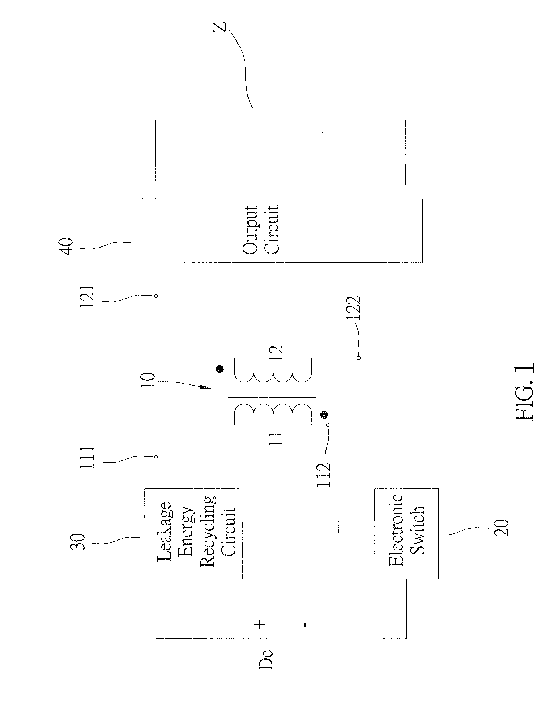
[0017]As shown in FIG. 1, a power conversion apparatus of the first preferred embodiment of the present invention is able to convert power of a direct current (DC) power supply Dc, and provide the converted power to a loading Z. The power conversion apparatus includes a transformer 10, an electronic switch 20, a leakage energy recycling circuit 30, and an output circuit 40.

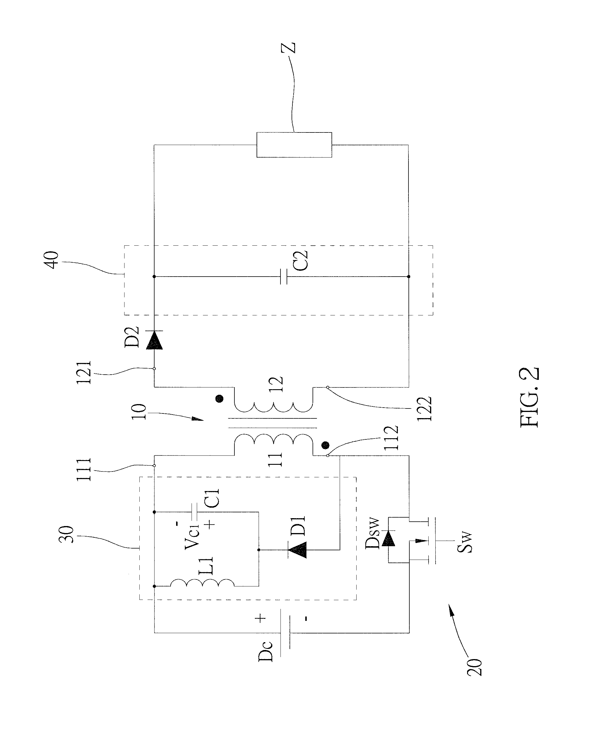
[0018]The transformer 10 has a primary winding 11 and a secondary winding 12, wherein the primary winding 10 receives the power of the DC power supply Dc, and the secondary winding 12 outputs the converted power. In more details, as shown in FIG. 2, the primary winding 11 has a first end 111 and a second end 112, and the secondary winding 12 has a third end 121 and a fourth end 122, wherein the first end 111 of the primary winding 11 is electrically connected to a positive terminal of the DC power supply Dc. In the preferred embodiment, the transformer 10 is a flyback transformer, and the primary winding 11 and th...


PUM


Abstract

A power conversion apparatus, which converts power of a DC power supply and provides it to the loading, includes a transformer, an electronic switch, a leakage energy recycling circuit, and a output circuit. The transformer has a primary winding, which receives the power, and a secondary winding, which outputs the converted power. An end of the electronic switch is electrically connected to the primary winding; another end thereof is electrically connected to the DC power supply. The leakage energy recycling circuit is electrically connected to the primary winding, and repeatedly and alternatively outputs power of positive and negative voltage. The circuit receives and stores leakage energy of the transformer, and feedbacks it to the transformer. The output circuit is electrically connected to the secondary winding to receive the converted power and to provide it to the loading.

Description

BACKGROUND OF THE INVENTION[0001]1. Technical Field[0002]The present invention relates generally to power conversion, and more particularly to a power conversion apparatus.[0003]2. Description of Related Art[0004]Typically, a conventional power conversion apparatus converts power with a transformer and other electronic components, and while the transformer works, it would generate corresponding magnetizing inductance and leakage energy, wherein leakage energy is a natural phenomenon which happens due to incomplete coupling of magnetic flux between the primary and secondary windings of the transformer. With wider air gap between the primary winding and the secondary winding, the coupling coefficient of the transformer becomes lower, which generates more leakage energy.[0005]In fact, leakage energy of a transformer can be seen as the parasitic inductance of an equivalent parasitic inductor which is in-series connected to an equivalent inductor of the primary winding. Therefore, while ...

Claims


Application Information

Patent Timeline
Patent Type & Authority Applications(United States)
IPC IPC(8): H02M3/335H02M1/00
CPCH02M3/33507H02M3/335H02M1/0048Y02B70/10
Inventor CHEN, PO-YENPAN, CHING-TSAIHUNG, TA-SHENG
Owner HEP TECH
Why Eureka
Try Eureka