
Low power frequency divider using dynamic modulated-load latch

a dynamic modulation and low-power technology, applied in the field of low-power latches, can solve the problems that conventional cml-based frequency dividers may consume a significant amount of power, and achieve the effects of reducing power consumption in frequency dividers, increasing load impedance, and reducing load impedan

Inactive Publication Date: 2016-01-07
QUALCOMM INC
View PDF3 Cites 1 Cited by
  • Summary
  • Abstract
  • Description
  • Claims
  • Application Information

AI Technical Summary

Benefits of technology

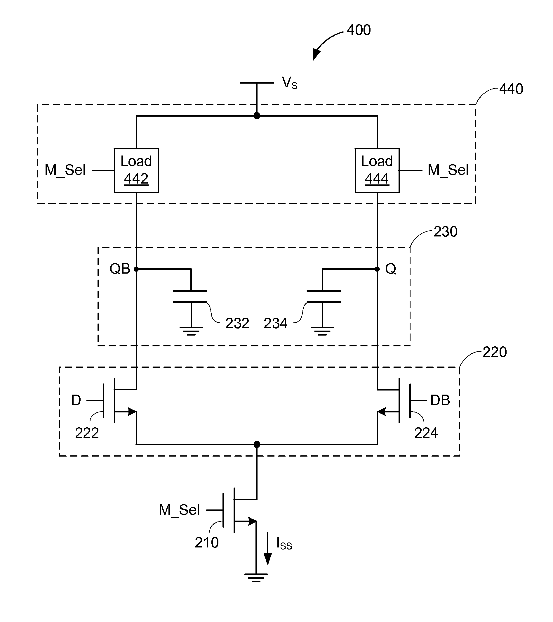
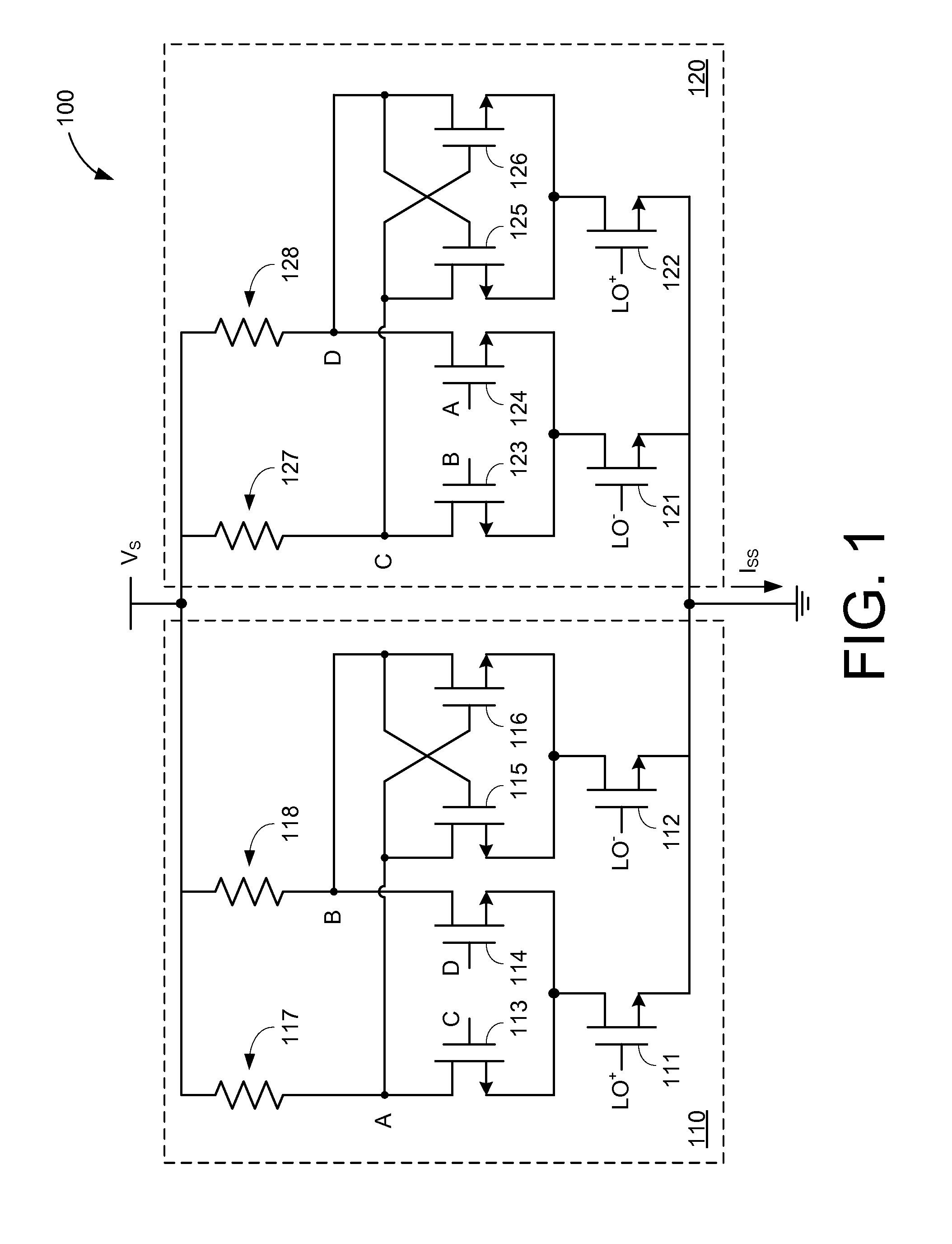
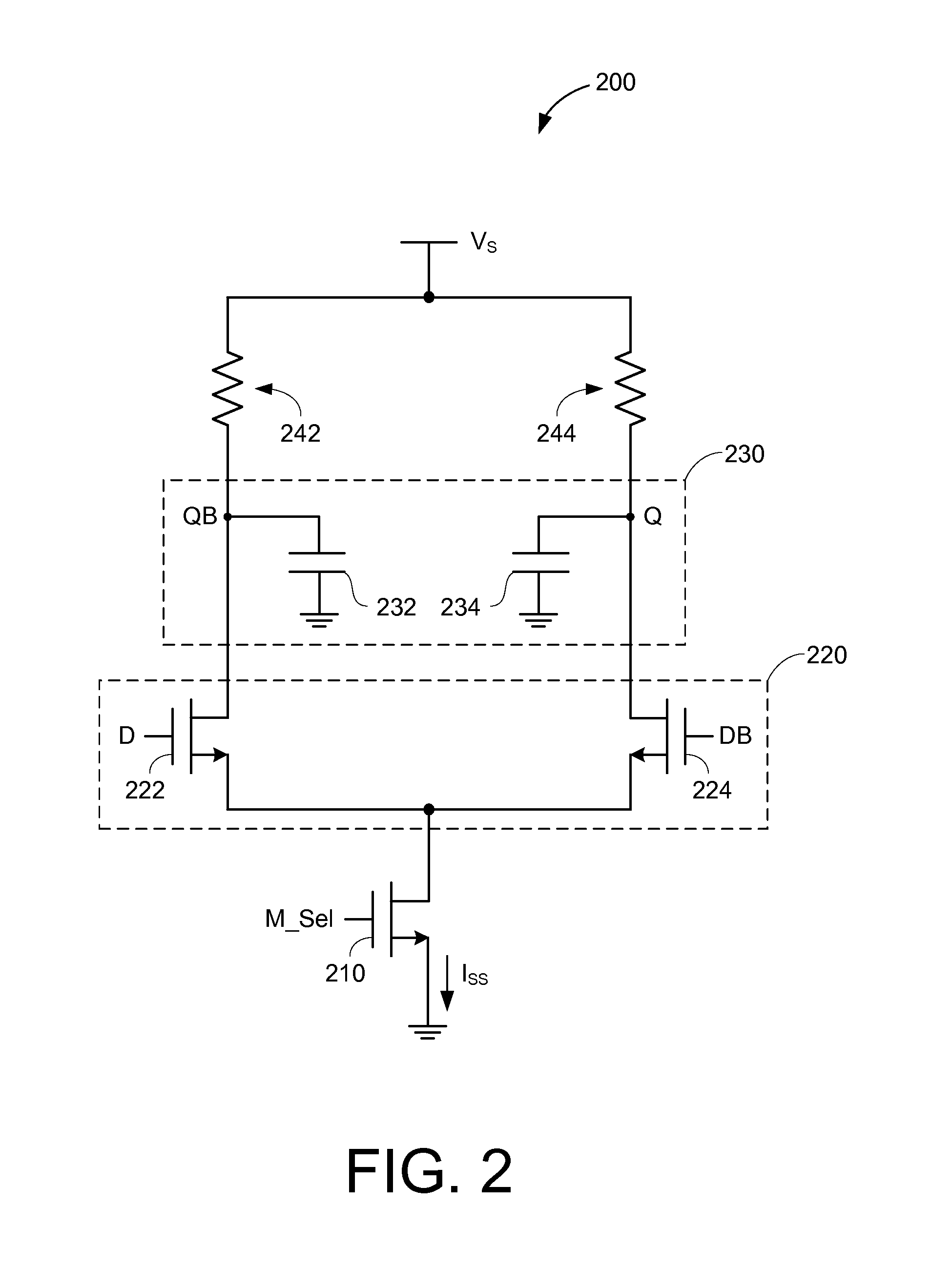
The patent describes a dynamic latch that reduces power consumption in frequency dividers. It includes a sense component to detect an input voltage and generate an output voltage based on the input voltage. The latch has a hold component to retain the output voltage. A transistor is coupled between the sense component and ground potential, and its operation depends on a mode select signal. When the mode select signal is in a first state, the transistor provides a tail current based on the signal. When the mode select signal is in a second state, the transistor performs a different function to decrease or increase the load impedance of the latch. This design can save power and improve performance.

Problems solved by technology

Conventional CML-based frequency dividers may consume a significant amount of power.

Method used


Image

  • Low power frequency divider using dynamic modulated-load latch
  • Low power frequency divider using dynamic modulated-load latch
  • Low power frequency divider using dynamic modulated-load latch

Examples


Embodiment Construction

[0018]In the following description, numerous specific details are set forth such as examples of specific components, circuits, and processes to provide a thorough understanding of the present disclosure. The term “coupled” as used herein means connected directly to or connected through one or more intervening components or circuits. Also, in the following description and for purposes of explanation, specific nomenclature is set forth to provide a thorough understanding of the present embodiments. However, it will be apparent to one skilled in the art that these specific details may not be required to practice the present embodiments. In other instances, well-known circuits and devices are shown in block diagram form to avoid obscuring the present disclosure. Any of the signals provided over various buses described herein may be time-multiplexed with other signals and provided over one or more common buses. Additionally, the interconnection between circuit elements or software blocks...


PUM


Abstract

A dynamic latch is disclosed that may reduce power consumption in frequency dividers while widening their frequency operation ranges. The dynamic latch includes a sense component to detect an input voltage in response to a first state of a mode select signal, and to generate an output voltage based, at least in part, on the input voltage; a hold component to retain the output voltage in response to a second state of the mode select signal; and a first transistor, coupled between the sense component and ground potential, including a gate responsive to the mode select signal.

Description

TECHNICAL FIELD[0001]The present embodiments relate generally to frequency dividers, and specifically to low-power latches that may be used to implement frequency dividers.BACKGROUND OF RELATED ART[0002]A frequency divider receives an input signal having a predefined frequency f and produces an output signal having a frequency f / n, where n is an integer value. Frequency dividers may be provided along the local oscillator (LO) distribution path in mobile communications systems to produce clock signals at a desired frequency.[0003]Current mode logic (CML) latches are commonly used in frequency divider implementations. CML latches are capable of bimodal operation. For example, a typical CML latch includes one set of transistors to sense or detect an input voltage during a “sensing mode,” and includes another set of transistors to retain a corresponding output voltage during a “holding mode.” The ability to seamlessly switch between sensing and holding a particular voltage makes CML lat...

Claims


Application Information

Patent Timeline
Patent Type & Authority Applications(United States)
IPC IPC(8): H03K3/012H03K3/356
CPCH03K3/012H03K3/356H03K3/356139
Inventor NGUYEN, THINH CATYANG, JEONGSIKWANG, SHENBICAKCI, ARASAVLA, ANUPVAKILI-AMINI, BABAK
Owner QUALCOMM INC
Learn More