Attachment for an electronic communications device

Inactive Publication Date: 2016-01-07
CLASSIC PROMOTIONS
View PDF3 Cites 8 Cited by
  • Summary
  • Abstract
  • Description
  • Claims
  • Application Information

AI Technical Summary

Benefits of technology

[0028]In embodiments, the conducting element includes various shaped segments of conducting material and may include V-shaped segments, chevron-shaped segments, linear segments, rectangular and/or triangular segments or any segments or combinations thereof that enable the conducting element to channel electromagnetic radiation to and from the electronic communications device such that the radiation is ported to and from the electronic communications device through the side of the device to which the attachment is attached and hence, reducing the exposure of the user to electromagnetic radiation emanating from and received by the electronic communications device.
[0029]An attachment according to the present invention effectively forms a bi-directional band pass filter which allows only signals with a particular frequency range to pass through the filter. The bi-directionality of the filter allows signals (within the relevant band of frequencies) to pass to and from the electronic communications device.
[0030]Careful selection of materials forming the conducting element, the

Problems solved by technology

Therefore, there is a concern by some users that the radiation from mobile phones may be harmful.
The need to carry a headset in addition to a mobile phone is also inconvenient and therefore many users tend not to use headset arrangements during telephone calls for this reason.
There is also a suggestion that headset arrangements comprised of earphones connected to the mobile phone via a conducting wire in which the earphones are directly inserted into a user's ears present, and potentially increase, the same dangers associated mobile phone radiation.
Many users therefore do not accept the use of such headset arrangements to be an acceptable solution to the problem.
However, hollow air tube headsets have a number of disadvantages.
Firstly, the need to carry the air tube headset is inconvenient and therefore many users tend not to use air tube headsets for this reason.
Secondly, many users report inferior sound transmission and sound quality with the use of such headsets and therefore avoid using them.
Unfortunately, these recommendations are rarely followed by users who generally press the mo

Method used


Image

  • Attachment for an electronic communications device
  • Attachment for an electronic communications device
  • Attachment for an electronic communications device

Examples


Embodiment Construction

[0039]Elements of the invention are illustrated in concise outline form in the drawings, showing only those specific details that are necessary to the understanding of the embodiments of the present invention, but so as not to clutter the disclosure with excessive detail that will be obvious to skilled readers.

[0040]In this patent specification, adjectives such as first and second, left and right, front and back, top and bottom, etc., are used solely to define one component or method step from another component or method step without necessarily requiring a specific relative position or sequence that is described by the adjectives.

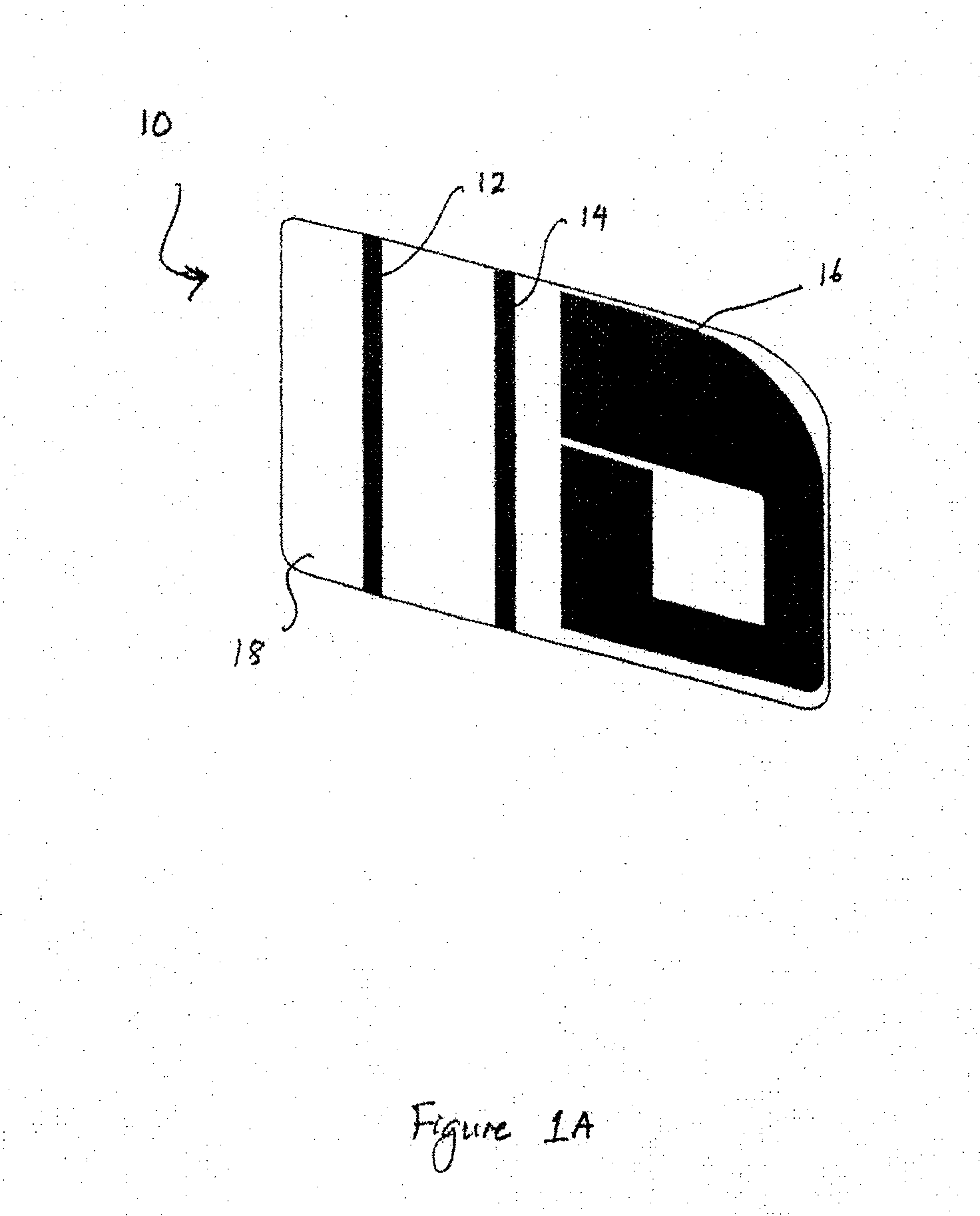
[0041]FIG. 1A illustrates a perspective view of a first conducting element (10). The conducting element (10) includes individual conducting sub elements (12, 14 and 16) that are attached to a flexible printed circuit board material (18).

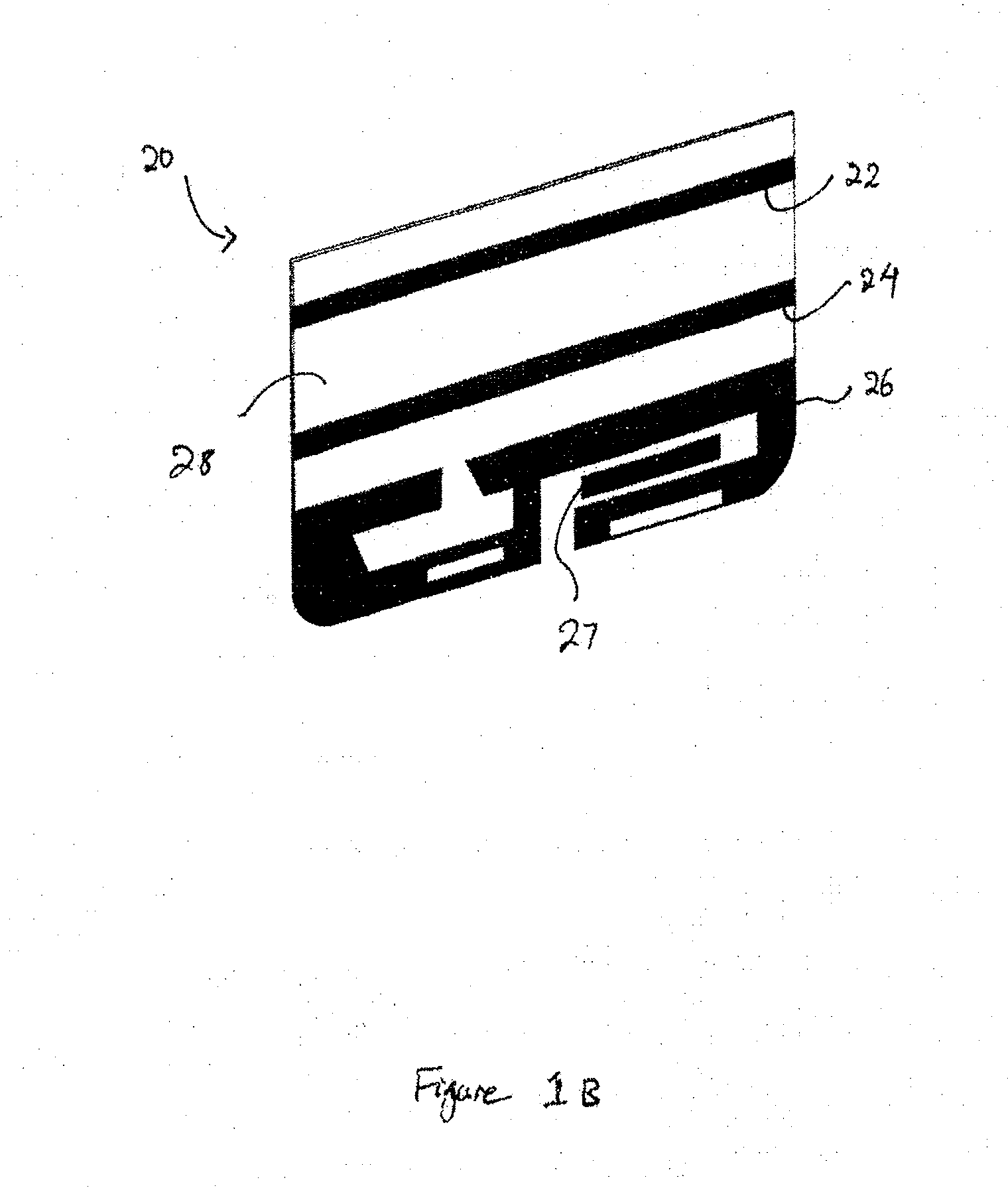
[0042]FIG. 1B illustrates a perspective view of a second conducting element (20). The conducting element (20) includes in...


PUM


Abstract

An attachment for an electronic communications device including a conducting element that is coated on one side with layers of material and securely affixed to a non-conducting substrate such that the overall dimensions and thickness of the attachment are sufficiently small that it may be attached to a surface of an electronic communications device whilst allowing the use of any protective casing preferred by the user.

Description

FIELD OF THE INVENTION[0001]The present invention relates to an attachment for an electronic communications device. In particular, the invention relates to an attachment including a passive conducting element for electromagnetic coupling with the electronic communications device.BACKGROUND TO THE INVENTION[0002]Mobile phones, and in particular, smart phones capable of transmitting and receiving both voice and data signals, are being used more often. Consequently, users are spending more time speaking to others using their mobile phones and hence, they are holding the mobile phone in close proximity to their head for increasingly greater cumulative periods of time.[0003]Mobile telephones use electromagnetic radiation to communicate with a base station. The World Health Organisation has classified mobile phone radiation as possibly carcinogenic and recommend that users reduce their exposure to the electromagnetic radiation emitted from mobile phones. Therefore, there is a concern by s...

Claims


Application Information

Patent Timeline
IPC IPC(8): H04B1/3827H01Q1/24
CPCH04B1/3838H04W88/02H01Q1/245H01Q1/526
Inventor LEIBOVICH, AARON
Owner CLASSIC PROMOTIONS
Why Eureka
Try Eureka