
Electrostatic membrane pump/transducer and methods to make and use same

a technology pump, which is applied in the direction of transducer details, electrical transducers, deaf-aid sets, etc., can solve the problems of ineffective low frequency sound, inability to efficiently produce high frequency sounds, and bulky speakers in parts, so as to reduce the complexity and cost reduce the contacting and wear of elements, and simplify the design of electrically conductive membrane transducers.

Active Publication Date: 2016-01-07
BRANE AUDIO LLC
View PDF1 Cites 16 Cited by
  • Summary
  • Abstract
  • Description
  • Claims
  • Application Information

AI Technical Summary

Benefits of technology

This patent describes a new design of an electrostatic membrane pump that uses an electrically conductive membrane to increase fluid pressure. The design includes a second metallic trace and a time-varying voltage to move the membrane in both directions, which enables the fluid to flow in both directions through the stator. This simultaneous deflection of the membrane in both directions results in higher fluid pressure than if the membrane were only deflected in one direction. Overall, this design improves the performance of the electrostatic membrane pump.

Problems solved by technology

These speakers are also bulky in part because large enclosures are used to muffle the sound radiating from the backside of the cone (which is out of phase with the front-facing audio waves).
Cone speakers also depend on mechanical resonance; a large “woofer” speaker does not efficiently produce high frequency sounds, and a small “tweeter” speaker does not efficiently produce low frequency sounds.
However, TA speakers are terribly inefficient, converting well under 1% of their electrical input into audio waves.
However, it has been found that such electrically conductive membrane transducers (of PCT US11 / 23618 application) have limitations because these systems requires air to flow from the back of the chip / wafer to the front of the chip / wafer.
Furthermore, these systems also require the valves to operate properly.
These two simplifications result in much lower complexity and cost.

Method used


Image

  • Electrostatic membrane pump/transducer and methods to make and use same
  • Electrostatic membrane pump/transducer and methods to make and use same
  • Electrostatic membrane pump/transducer and methods to make and use same

Examples


Embodiment Construction

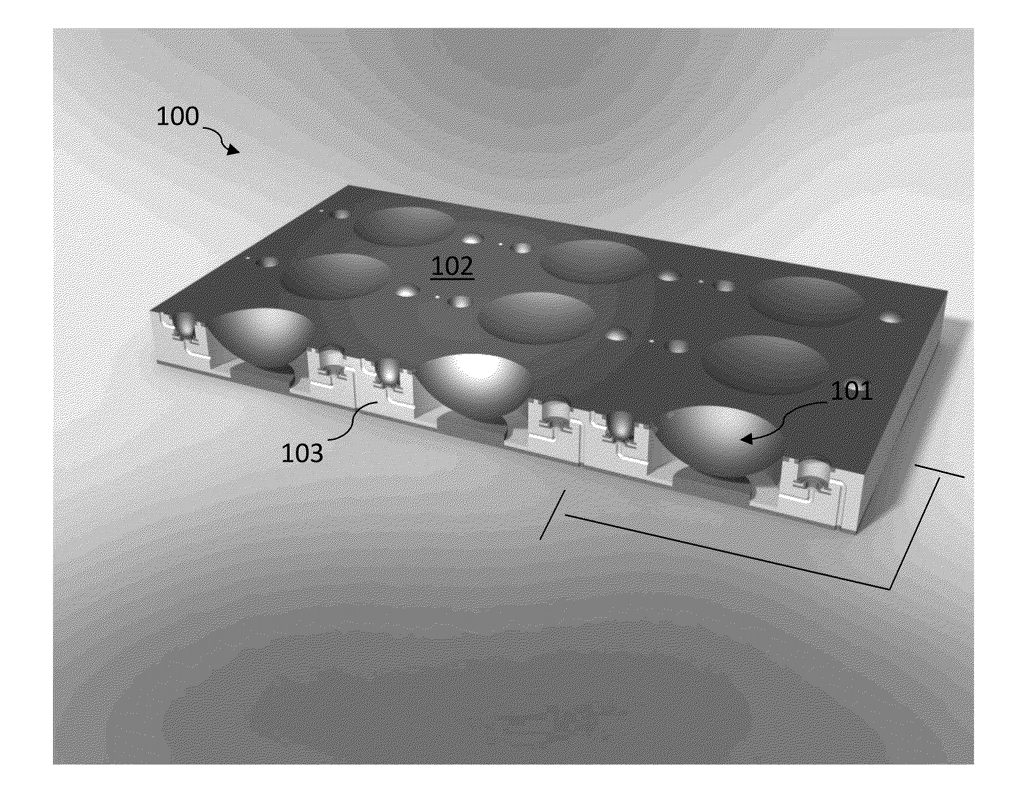
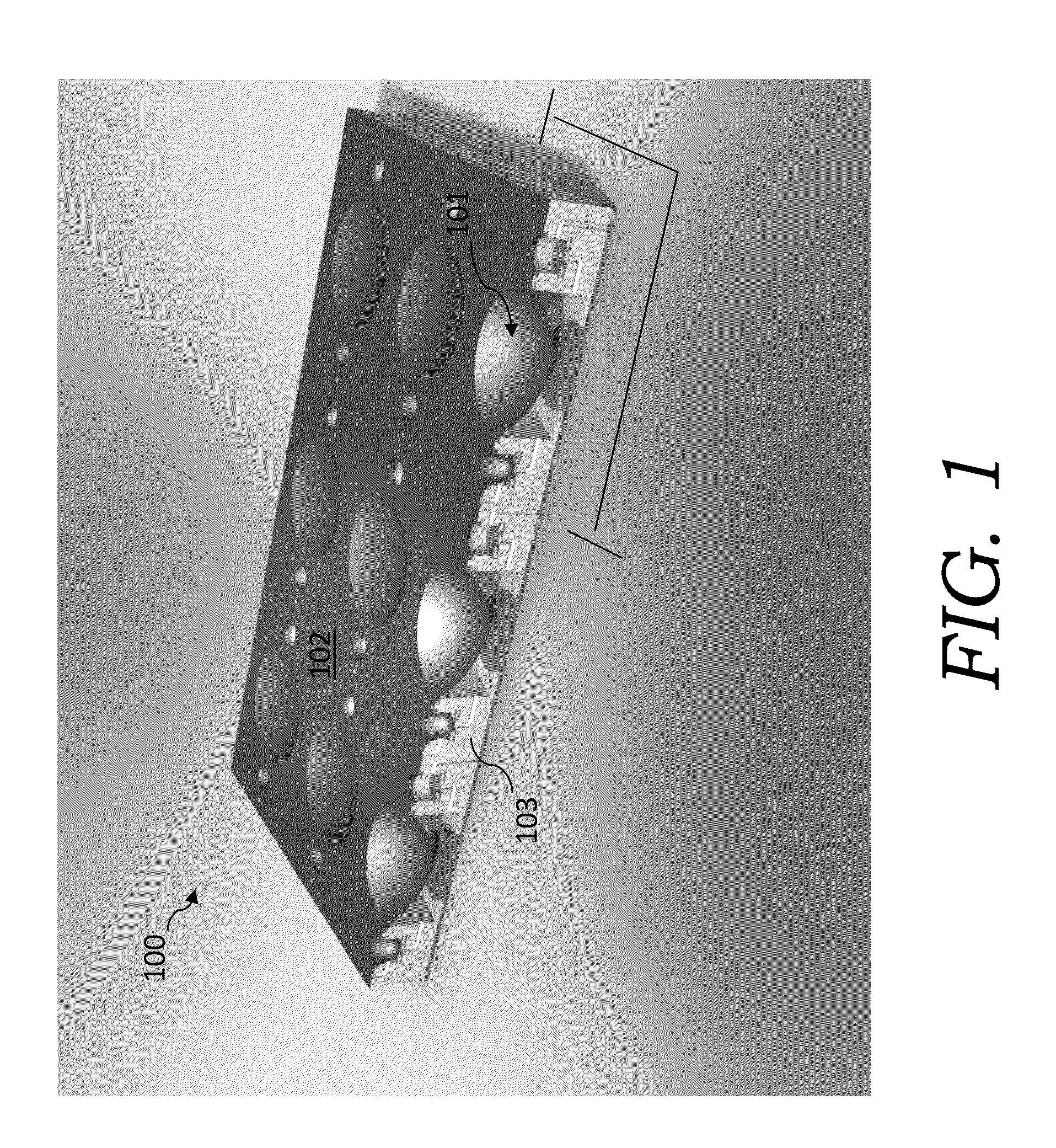
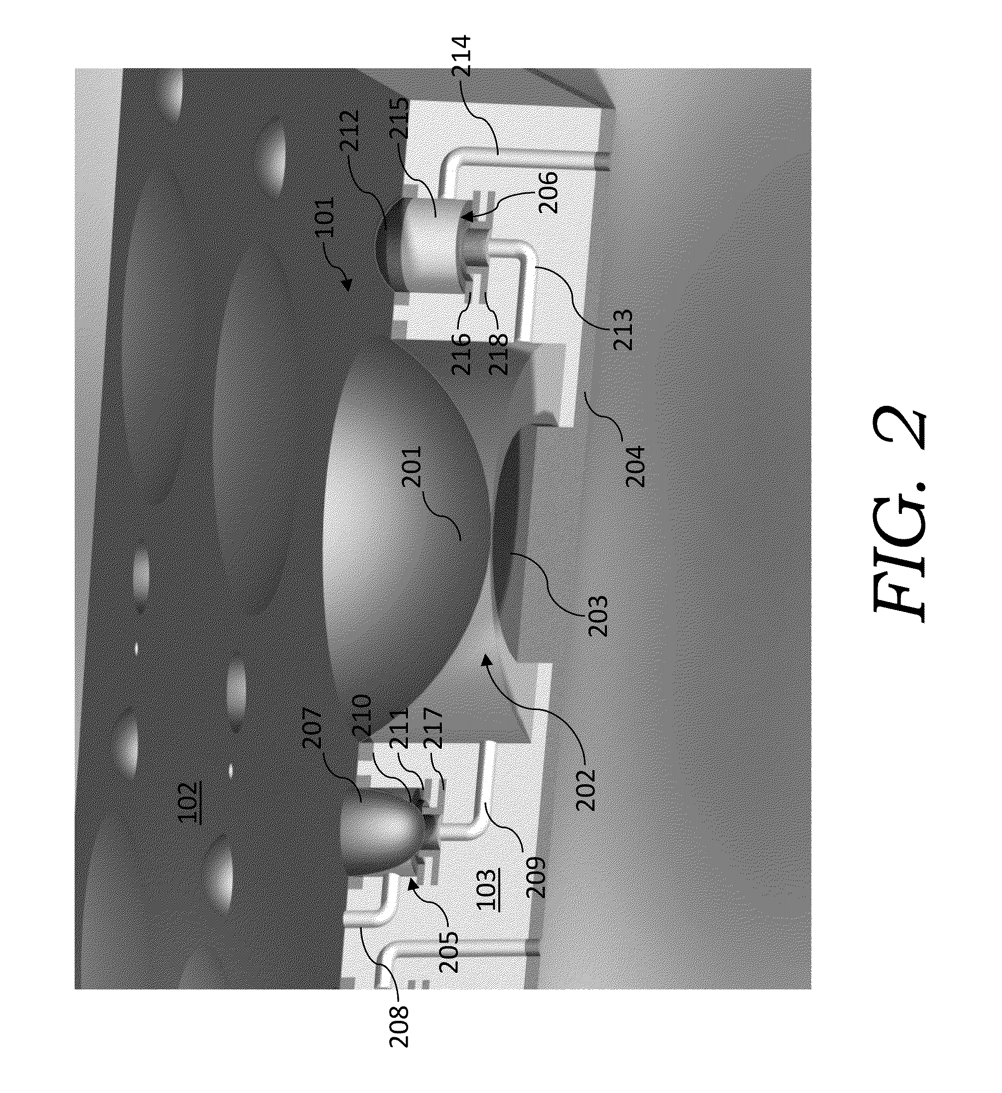
[0236]The present invention relates to an improved electrically conductive membrane transducer, such as, for example, an improved graphene membrane transducer. The improved electrically conductive membrane transducer does not require air (or other fluid) to flow from the back of the chip / wafer to the front of the chip / wafer. Furthermore, the improved electrically conductive membrane does not require valves to operate. Other advantages of the present invention is that the electrically conductive membrane transducer can draw / push air in / out the same vents (allowing everything to be on one side of the chip / wafer if desired). These simplifications result in much lower complexity and cost.

[0237]Also, there is no contacting / wear elements in the current invention.

[0238]Moreover, the electrically conductive membrane transducer sends audio waves out from one face of a chip; thus there is no longer any requirement to mount the device in a bulky enclosure (the backside of conventional cone spe...


PUM


Abstract

An improved electrostatic membrane pump / transducer having an array of electrostatic membrane pump transducers that utilize a venturi channel. The electrically conductive membrane of the electrostatic membrane pump transducers can be a polymer membrane coated with a conductive coating. The electrostatic membrane pump transducers can be optionally controlled such that one set is out of phase with another set.

Description

CROSS-REFERENCE TO RELATED PATENT APPLICATIONS[0001]This application is a continuation-in-part of U.S. patent application Ser. No. 14 / 047,813, filed Oct. 7 2013, which is entitled “Electrically Conductive Membrane / Pump Transducer And Methods To Make And Use Same.” That application is a continuation-in-part of International Patent Application No. PCT / 2012 / 058247, filed Oct. 1, 2012, which designated the United States and claimed priority to provisional U.S. Patent Application Ser. No. 61 / 541,779, filed on Sep. 30, 2011, each of which patent applications is entitled “Electrically Conductive Membrane Transducer And Methods To Make And Use Same.” All of these above-identified patent applications are commonly assigned to the Assignee of the present invention and are hereby incorporated herein by reference in their entirety for all purposes.TECHNICAL FIELD[0002]The present invention relates to an electrostatic conductive membrane pump / transducer having an array of electrostatic membrane p...

Claims


Application Information

Patent Timeline
IPC IPC(8): H04R19/02H04R1/26H04R7/02
CPCH04R19/02H04R7/02H04R2400/13H04R2307/025H04R1/26H04R1/24H04R1/38H04R23/00
Inventor PINKERTON, JOSEPH, F.
Owner BRANE AUDIO LLC
Learn More