Method for manufacturing drive shaft

a technology of drive shaft and manufacturing method, which is applied in the direction of manufacturing tools, drawing dies, shaping tools, etc., can solve the problems of large area of shrinking apparatus, weakened force in the axial direction of metallic pipe, and cracks between shrunk portions and parts that are not shrunk, so as to reduce manufacturing cost and weight, reduce bending, strain and vibration

Active Publication Date: 2016-01-14
JUNG JONG HOON
View PDF0 Cites 3 Cited by
  • Summary
  • Abstract
  • Description
  • Claims
  • Application Information

AI Technical Summary

Benefits of technology

[0029]According to the method for manufacturing a drive shaft, it is possible to obtain less bending, strain, vibrations and cracks which used to happen in the course of shrinking when manufacturing a drive shaft. The investment in manufacturing facilities may be saved by lowering manufacturing cost and weight and by simplifying manufacturing processes. It is possible to reduce the area where the shrinking apparatus occupies.

Problems solved by technology

Since a plurality of shrinking forms are used, the shrinking apparatus may need large area.
In addition, when shrinking the pipes with the aid of a plurality of shrinking forms, the force in the axial direction of the metallic pipe may be weakened, for which the axis of the metallic pipe may be distorted or the axes of the shrunk portions and the portions where are not shrunk may deviate from each other.
In addition, since the shrinking is generally performed with the aid of the shrinking forms while applying force in an axial direction of the metallic pipe, over force may be applied in an axial direction of the metallic pipe, so cracks may occur between the shrunk portions and the portions where are not shrunk.

Method used


Image

  • Method for manufacturing drive shaft
  • Method for manufacturing drive shaft
  • Method for manufacturing drive shaft

Examples


Embodiment Construction

[0040]Hereinafter, an exemplary embodiment of the present invention is described with reference to the accompanying drawings according to a preferred embodiment of the invention. It should be understood that the dimension, the shape, etc. provided in the drawings may be exaggerated for the sake of simplicity and convenience in the descriptions. The terminology used herein may change subject to the intension or convention of a user or an operator. The definitions of the terminology used herein should be interpreted as presenting the meaning and concept corresponding to the technical ideas of the present invention.

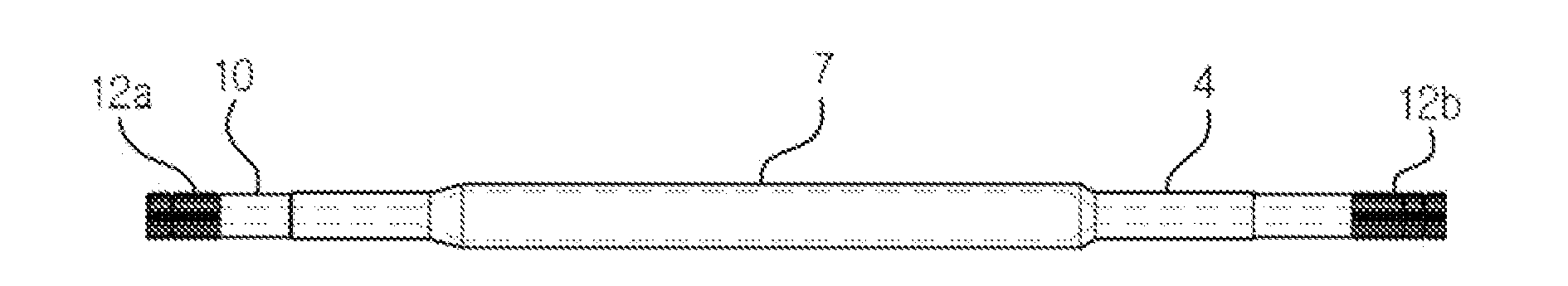
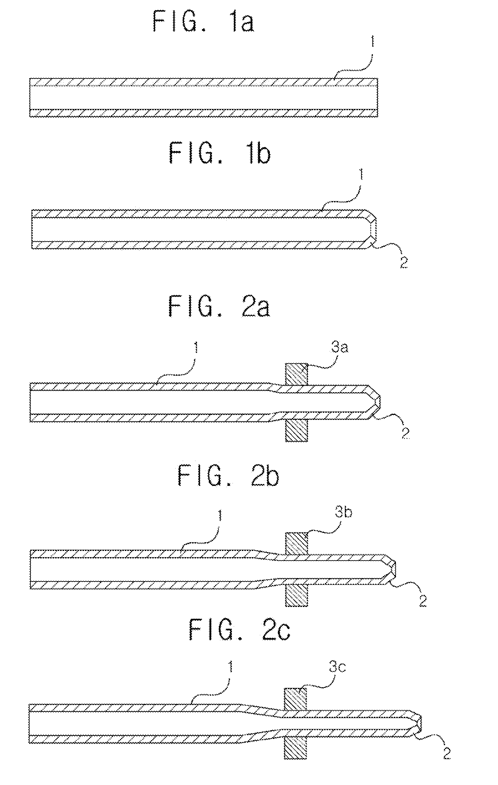
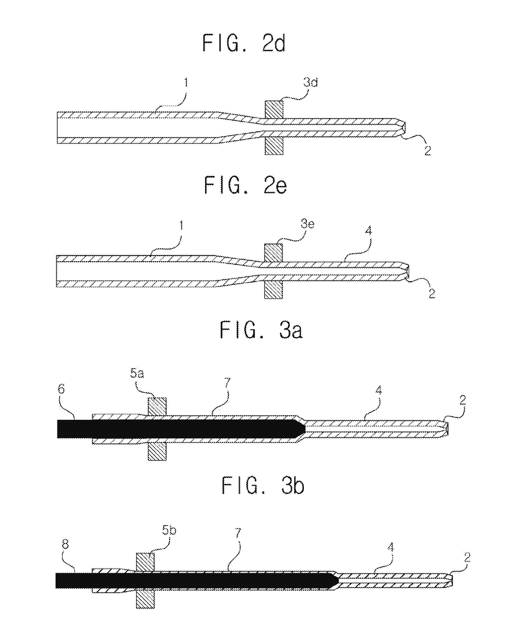
[0041]FIGS. 1a to 6 are cross sectional and enlarged views illustrating a procedure for manufacturing a drive shaft according to an exemplary embodiment of the present invention.

[0042]FIG. 1a is a cross sectional view illustrating a metallic shaft used for manufacturing a drive shaft.

[0043]Referring to FIG. 1, a metallic pipe 1 used for manufacturing a drive shaft is formed ...


PUM

PropertyMeasurementUnit
strengthaaaaaaaaaa
thicknessaaaaaaaaaa
compression forceaaaaaaaaaa

Abstract

Disclosed in a method for manufacturing a drive shaft which comprises forming a first shaft unit by shrinking one side of a metallic pipe which has a uniform first strength; decreasing the thickness of an intermediate portion of the metallic pipe by drawing the intermediate portion of the metallic pipe which is integral with the first shaft unit forming at an inner side surface of the other side of the metallic pipe a strength decrease unit which has a second strength smaller than the first strength, by heat-treating by a predetermined distance the inner side surface of the other side being opposite to one side of the metallic pipe; and forming a second shaft unit without transforming any portion of the intermediate portion by shrinking the metallic pipe which has the strength decrease unit, wherein the second shaft unit is formed by applying compression force to a portion where the strength decrease unit in the metallic pipe is formed, in a predetermine direction being vertical with respect to the axial direction of the metallic pipe.

Description

TECHNICAL FIELD[0001]The present invention relates to a method for manufacturing a drive shaft, and particularly to a method for manufacturing a drive shaft which makes it possible to prevent the bending and strain of as metallic pipe which used to happen when forming as drive shaft, in such a way to shrink a metallic pipe, while obtaining less weight, vibrations, manufacturing cost and investment in manufacturing facilities as well as preventing the bending of a shaft in the course of shrinking a metallic pipe.BACKGROUND ART[0002]In case of a rear wheel drive or four wheel drive vehicles, the power of a vehicle engine is transferred through as transmission and a drive shaft connected to the transmission to differential gears of a vehicle, and the vehicle may be driven based on a rear wheel drive or a four wheel drive by means of the driving force transferred through the differential gears to the rear wheels of the vehicle.[0003]Here, since the torsion stress applied to a drive shaf...

Claims


Application Information

Patent Timeline
Patent Type & Authority Applications(United States)
IPC IPC(8): B21C1/24B21C3/02B21C3/16B21C9/00F16C3/02
CPCB21C1/24B21C3/16F16C3/02B21C9/00B21C3/02B21C1/003B21C1/18B21D41/04B21D53/84B21D53/88B21K1/10C21D2221/00F16C3/023F16C2220/42
Inventor JUNG, JONG HOONKIM, DONG GUN
Owner JUNG JONG HOON
Why Eureka
Try Eureka