Precoated steel plate, welded blank, part and methods

a technology of prefabricated steel and welded blanks, applied in the direction of railway components, fastening means, nuclear engineering, etc., can solve the problems of prone to corrosion and difficulty in fabricating methods, and achieve good corrosion resistance

Active Publication Date: 2016-01-14
ARCELORMITTAL INVESTIGACION Y DESARROLLO SL
View PDF2 Cites 17 Cited by
  • Summary
  • Abstract
  • Description
  • Claims
  • Application Information

AI Technical Summary

Benefits of technology

The invention describes a method to prevent the formation of intermetallic areas in welded steel assemblies, which can lead to rupture under static or dynamic conditions. The method also improves corrosion resistance. It involves using a pre-coated steel blank or a heat treatment process that converts the pre-coating into an intermetallic alloy compound that protects against corrosion and decarburization. The method involves welding the steel blank with a coated face and then eliminating the metal alloy layer on the face through brushing or laser beam removal. The resultant welded and heat treated parts have good corrosion resistance and are suitable for use in various applications where high strength and durability are required.

Problems solved by technology

However, this fabrication method runs into considerable difficulties: when welding coated steel blanks, a portion of the initial surface pre-coating is transferred into the molten area created by the welding operation.
However, eliminating this source itself gives rise to a serious problem: the precoated area on either side of the future welded joint can be eliminated, for example by a mechanical process.
These are areas that tend to corrode when the parts go into service because they are not protected by any coating.

Method used


Image

  • Precoated steel plate, welded blank, part and methods
  • Precoated steel plate, welded blank, part and methods
  • Precoated steel plate, welded blank, part and methods

Examples


example

[0105]The following embodiments show by way of example other advantages conferred by the present invention. They concern a cold-rolled steel strip 1.5 mm thick, with the following composition by weight:

TABLE 1Composition of the steel (% by weight)CMnSiSPAlCrTiB0.224 1.1600.2260.0050.0130.044 0.1890.0410.0031

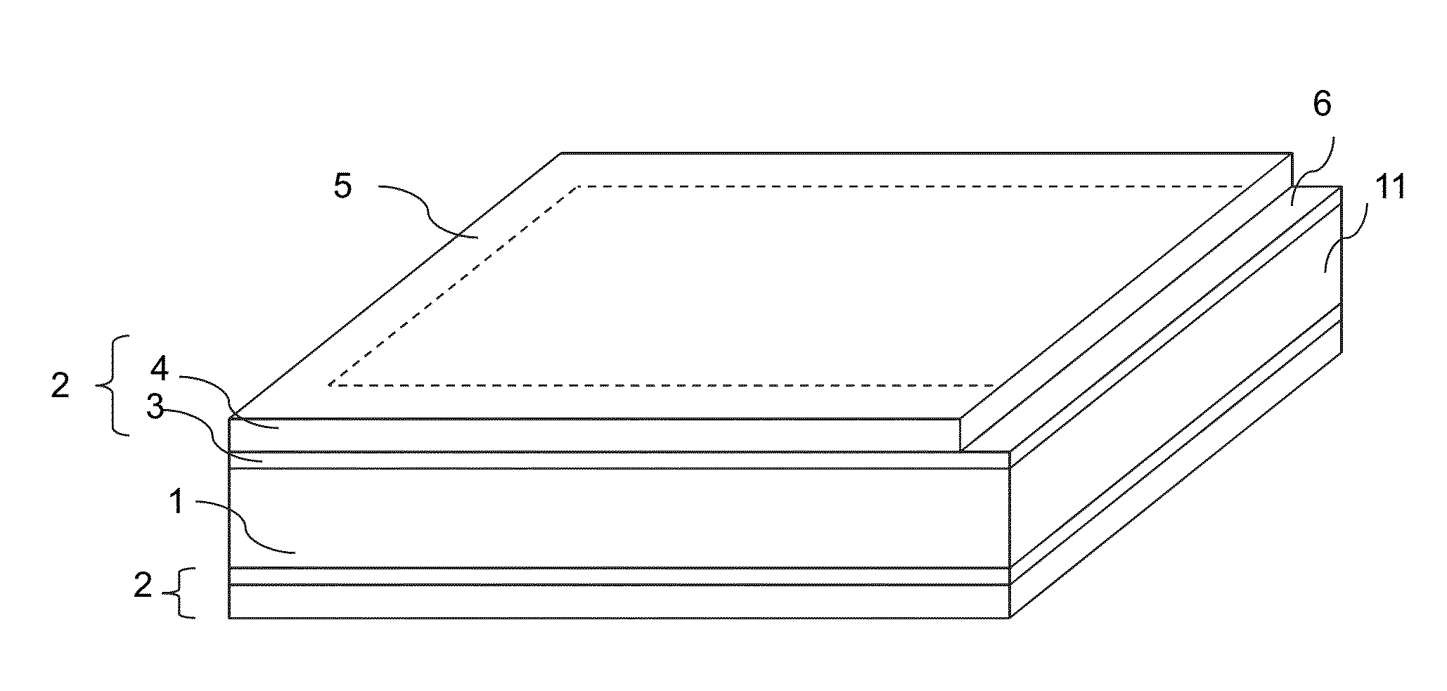
[0106]The steel strip was precoated by dipping it in a molten bath of an aluminum alloy containing 9.3% of silicon and 2.8% of iron, the remainder consisting of aluminum and inevitable impurities. The strip was then cut into plates with a format of 300×500 mm2. These have on each face a precoat comprising a layer of intermetallic alloy comprising mostly Fe2Al3, Fe2Al5 and FexAlySiz. This 5 micrometers thick layer in contact with the steel substrate has a 20 micrometers thick layer of Al—Si metal alloy on top of it.

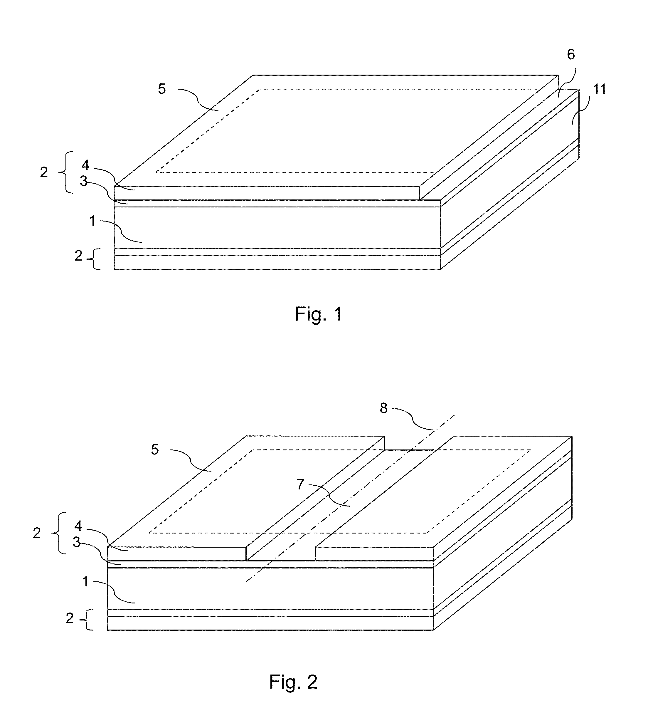
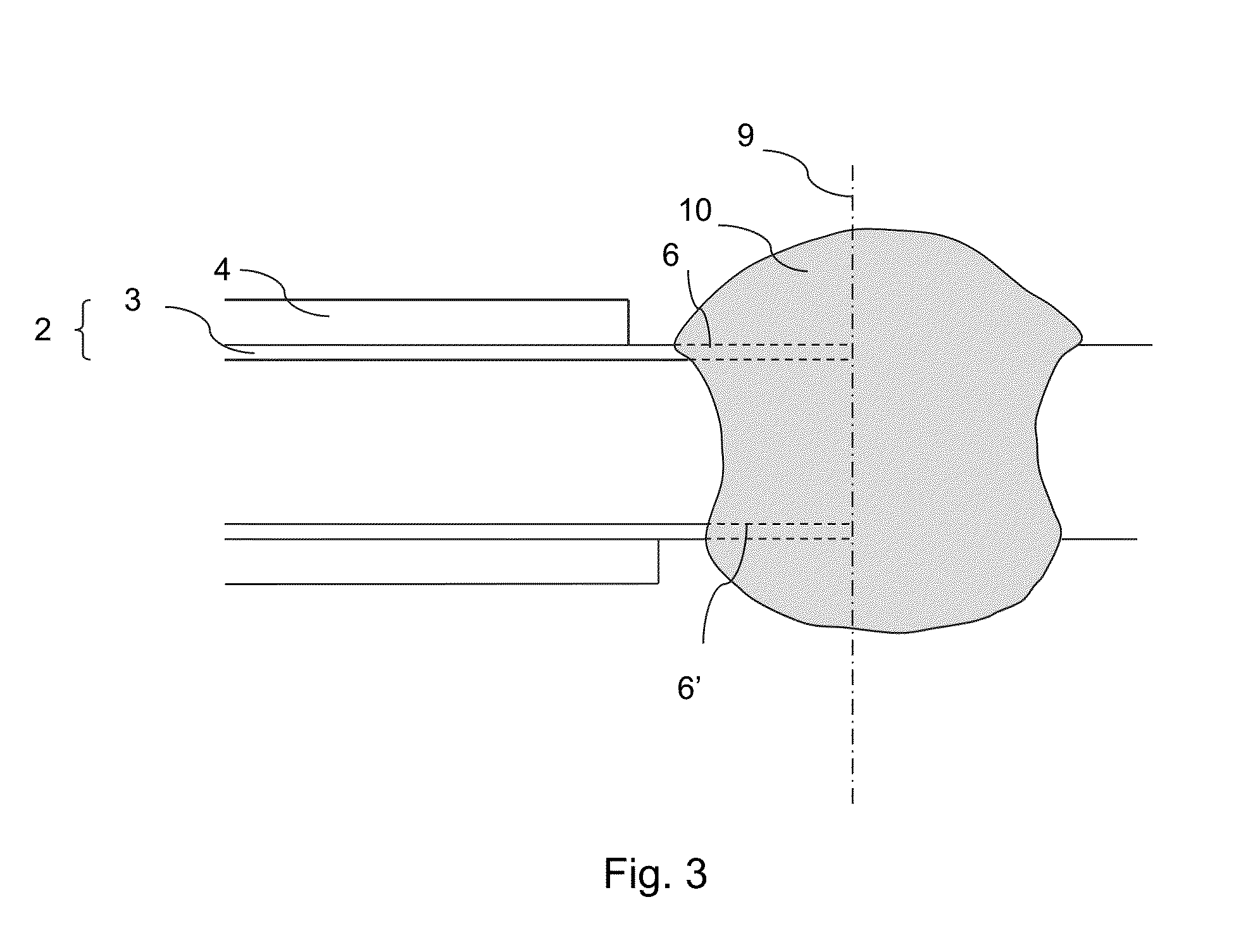
[0107]Before laser beam welding, four different preparation methods were used:[0108]Method I (according to the present invention): the Al—Si metal alloy layer was remov...


PUM

PropertyMeasurementUnit
tensile strengthaaaaaaaaaa
elongationaaaaaaaaaa
impuritiesaaaaaaaaaa

Abstract

A method of fabricating a precoated steel plate, the method including coating a steel plate by dipping the steel plate in a molten bath to obtain a precoat upon the steel plate, wherein the precoat includes an intermetallic alloy layer and a metal alloy layer. The intermetallic alloy layer is topped by the metal alloy layer. On at least one face of the plate, the metal alloy layer is removed in an area at a periphery of the plate using a laser beam, while leaving at least part of the intermetallic alloy layer in the area. The at least part of the intermetallic layer in the area has a thickness between 3 and 10 micrometers thick.

Description

CROSS REFERENCE TO RELATED APPLICATIONS[0001]This is a continuation of U.S. patent application Ser. No. 14 / 070,132, filed Nov. 1, 2013 and U.S. patent application Ser. No. 13 / 311,731 filed on Dec. 6, 2011 which are continuations of U.S. Pat. No. 8,614,008 issued on Dec. 24, 2013, which is a national stage application of PCT / FR2007 / 00536 filed on Mar. 29, 2007 which claims the benefit of PCT / FR2006 / 000898 filed on Apr. 19, 2006, the entire disclosures of which are hereby incorporated by reference herein.[0002]The invention concerns the fabrication of plates or blanks of coated steel intended to be welded and then heat treated to obtain parts having good mechanical characteristics and good corrosion resistance.BACKGROUND[0003]Some applications require steel parts combining high mechanical strength, high impact resistance and good corrosion resistance. This type of combination is particularly desirable in the automotive industry which requires a significant reduction in vehicle weight ...

Claims


Application Information

Patent Timeline
Patent Type & Authority Applications(United States)
IPC IPC(8): B23K26/362B23K26/40C22C21/02C22C38/00C22C38/02C22C38/04C22C38/06C22C38/28C22C38/32C23C2/12
CPCB23K26/362C22C38/32C22C38/28C22C38/06C23C2/12C22C38/02C22C38/002C22C21/02B23K26/40C22C38/04B23K2101/18B23K2101/34B23K2103/04B23K2103/10B23K2103/50B23K9/23B23K33/00C23C2/26C23C28/021B23K26/32B23K2103/08Y10T428/12229Y10T428/12271Y10T428/12389Y10T428/12396Y10T428/12486Y10T428/12493Y10T428/12757Y10T428/12764Y10T428/12972Y10T428/12979Y10T428/2495Y10T428/24967Y10T428/24975Y10T428/26Y10T428/263Y10T428/264Y10T428/265B32B15/012C21D1/00C21D6/002C21D6/005C21D6/008C21D9/50C21D2211/008C22C38/08F16B5/08
Inventor CANOURGUES, JEAN-FRANCOISPIC, AURELIENVERRIER, PASCALVIERSTRAETE, RENEEHLING, WOLFRAMTHOMMES, BERND
Owner ARCELORMITTAL INVESTIGACION Y DESARROLLO SL
Why Eureka
Try Eureka