
Electrical connector for an anode

an anode and electric connector technology, applied in the direction of connections, basic electric elements, electric apparatus, etc., to achieve the effect of preventing damage to the deformable member and minimising the transfer of forces

Active Publication Date: 2016-04-12
FUGRO SUBSEA SERVICES
View PDF16 Cites 1 Cited by
  • Summary
  • Abstract
  • Description
  • Claims
  • Application Information

AI Technical Summary

Benefits of technology

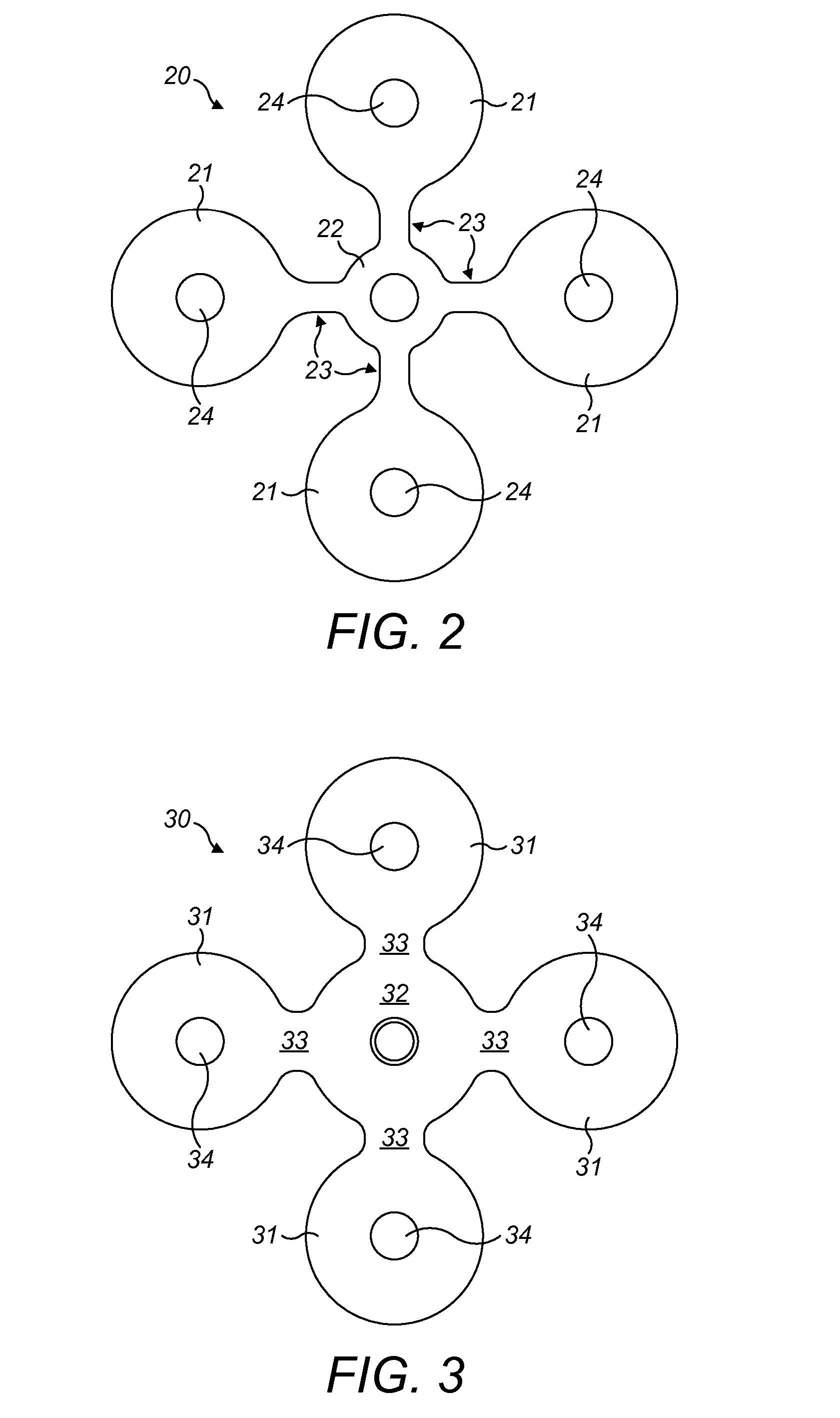
The patent describes a connector for protecting metal structures on the sea floor from corrosion. The connector has magnet devices that align with the surface of the metal structure to create a reliable electrical connection. The magnet devices are held in place by a deformable member that allows them to move relative to each other and align with the surface. The deformable member is made of a thin material that allows for bending and deformation. The connector also has a manipulation plate and an electrical contact plate that can move relative to each other to accommodate changes in the surface being protected. The manipulation plate and electrical contact plate have heads for each magnet device to allow for limited movement. The provision of the manipulation plate and its interconnection with the magnet devices allows for high forces to be transferred directly to the magnet devices while minimizing damage to the deformable member.

Problems solved by technology

However, typically the extent of movement that is permitted by the manipulation plate is limited to a particular range, and typically substantial movements of one of the magnet devices to displace it out of the same general plane as the other magnet devices is typically limited by the manipulation plate to within the deformable characteristics of the deformable member, so that the relative movement of the magnet devices does not disrupt the electrical connection between the magnet devices.

Method used


Image

  • Electrical connector for an anode
  • Electrical connector for an anode
  • Electrical connector for an anode

Examples


Embodiment Construction

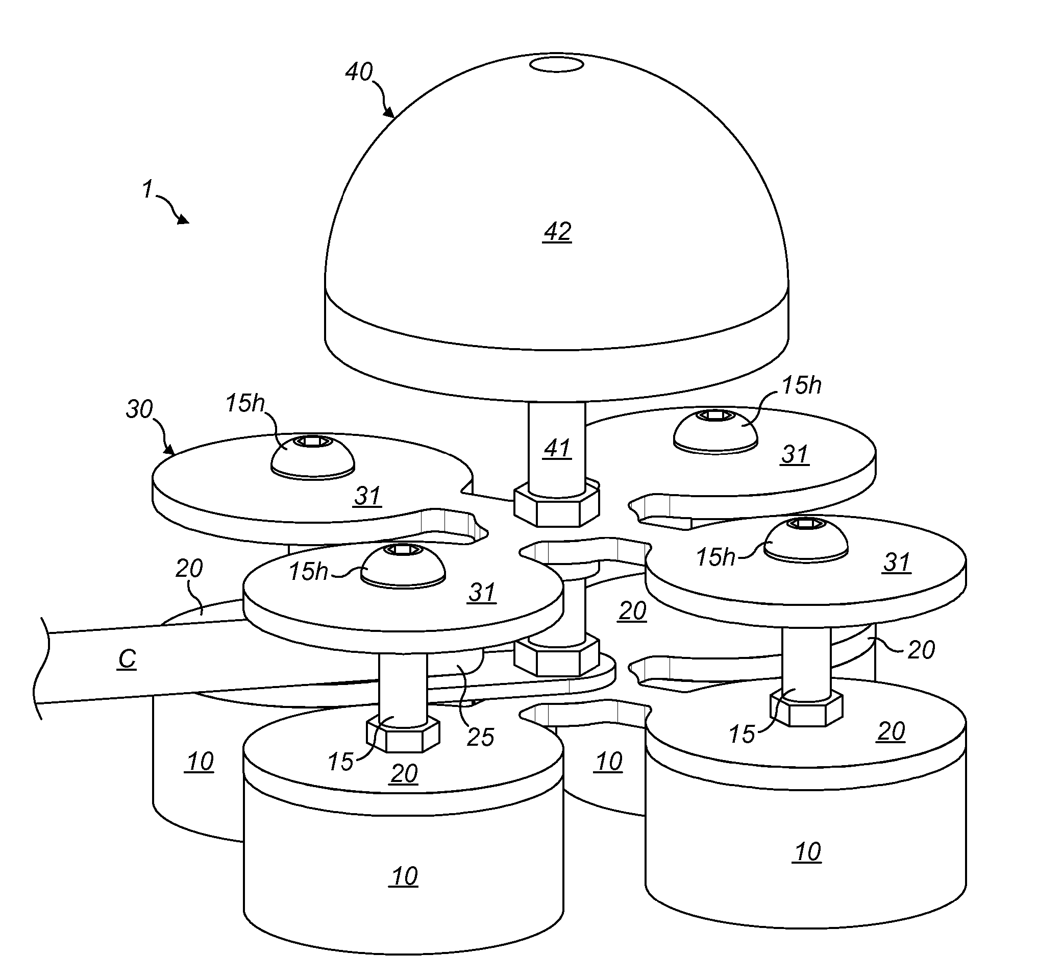
[0042]Referring now to the drawings, an electrical connector 1 has four magnet devices 10 arranged substantially equidistantly from one another in a general square pattern. The magnet devices 10, shown in more detail in FIG. 4, comprise generally circular discs having flat upper and lower faces, and having an inner core of magnetic material, typically a rare earth magnetic material such as neodymium, and substantially encased by an external casing 11. Different examples can have different numbers of magnet devices 10. Typically the external casing 11 in this example is formed from stainless steel, although other conductive metals particularly those that are resistant to corrosion can be used. Typically each magnet device 10 has a central aperture 14 in the disc, which is internally threaded in at least a part of its bore to receive and retain a fixing such as a shaft of a bolt which will be described later. Optionally, the bore of the aperture 14 is only partially threaded and has a...


PUM

PropertyMeasurementUnit
magnetic forcesaaaaaaaaaa
ductileaaaaaaaaaa
forceaaaaaaaaaa

Abstract

An electrical connector for an anode has a terminal for an electric cable, at least two magnet devices for attracting the connector onto a metal structure, a plate electrically connecting the magnet devices to one another and to the terminal, and a deformable member connecting the magnet devices. When the connector connects an anode to a surface, the magnet forces draw the magnet devices against the surface in order to make up the connection. The deformable member allows relative movement of the magnet devices, permitting them to align themselves in an optimum configuration to maximize the surface area of the magnet devices that are in contact with the metal structure, providing a large electrical conduit between the connector and the cable connected to the terminal, and allowing for more reliable electrical connection between the anode and the structure.

Description

BACKGROUND[0001]1. Technical Field[0002]This invention relates to an apparatus and method for making electrical connections from an anode to a subsea structure for the purpose of cathodic protection of the subsea structure by sacrificial corrosion of the anode.[0003]2. Description of Related Art[0004]Anodes are frequently connected to metal structures used in and on the sea, to protect the integrity of the metal structure by cathodic protection. Anodes are formed from metals which sacrificially corrode in preference to the metal structure, which functions as the cathode in the electrochemical circuit formed between the anode and the metal structure. The anode is typically replaced periodically as it corrodes.[0005]Cathodic protection typically requires an electrical connection between the anode and the structure being protected. Connection of anodes to submerged metal structures such as legs for platforms is typically accomplished by bolting or welding the anode connections in place...

Claims


Application Information

Patent Timeline
Patent Type & Authority Patents(United States)
IPC IPC(8): H01R11/30C23F13/00C23F13/20
CPCH01R11/30C23F13/005C23F13/20C23F2213/31Y10T29/49117
Inventor HARVEY, WILLIAM IAN
Owner FUGRO SUBSEA SERVICES
Learn More