Composite airfoil metal leading edge assembly

a technology of metal leading edge and composite airfoils, which is applied in the direction of machines/engines, stators, liquid fuel engines, etc., can solve the problems of high stress on the the compressor, the stator vanes and rotating blades of the turbine may become highly stressed, and the composite material is generally more prone to damage, so as to improve the erosion and impact characteristics of the composite foil and the effect of lighter weight composite material

Inactive Publication Date: 2016-01-14
GENERAL ELECTRIC CO
View PDF3 Cites 11 Cited by
  • Summary
  • Abstract
  • Description
  • Claims
  • Application Information

AI Technical Summary

Benefits of technology

[0009]According to aspects of the present embodiments, a metal leading edge assembly is applied to a composite airfoil. The composite airfoil may be utilized at various locations within the gas turbine engine. The metal leading edge assembly improves erosion and impact characteristics of the composite foil while allowing for the lighter weight composite material to be utilized.

Problems solved by technology

Due to extreme temperatures of the combustion gas flow path and operating parameters, the stator vanes and rotating blades in both the turbine and compressor may become highly stressed with extreme mechanical and thermal loading.
Additionally, foreign objects occasionally pass by these components with airflow.
Such composites however are generally more prone to damage from foreign objects passing through the airfoil area and are more susceptible to damage from higher operating temperatures.

Method used


Image

  • Composite airfoil metal leading edge assembly
  • Composite airfoil metal leading edge assembly
  • Composite airfoil metal leading edge assembly

Examples


Embodiment Construction

[0022]Reference now will be made in detail to embodiments provided, one or more examples of which are illustrated in the drawings. Each example is provided by way of explanation, not limitation of the disclosed embodiments. In fact, it will be apparent to those skilled in the art that various modifications and variations can be made in the present embodiments without departing from the scope or spirit of the disclosure. For instance, features illustrated or described as part of one embodiment can be used with another embodiment to still yield further embodiments. Thus it is intended that the present invention covers such modifications and variations as come within the scope of the appended claims and their equivalents.

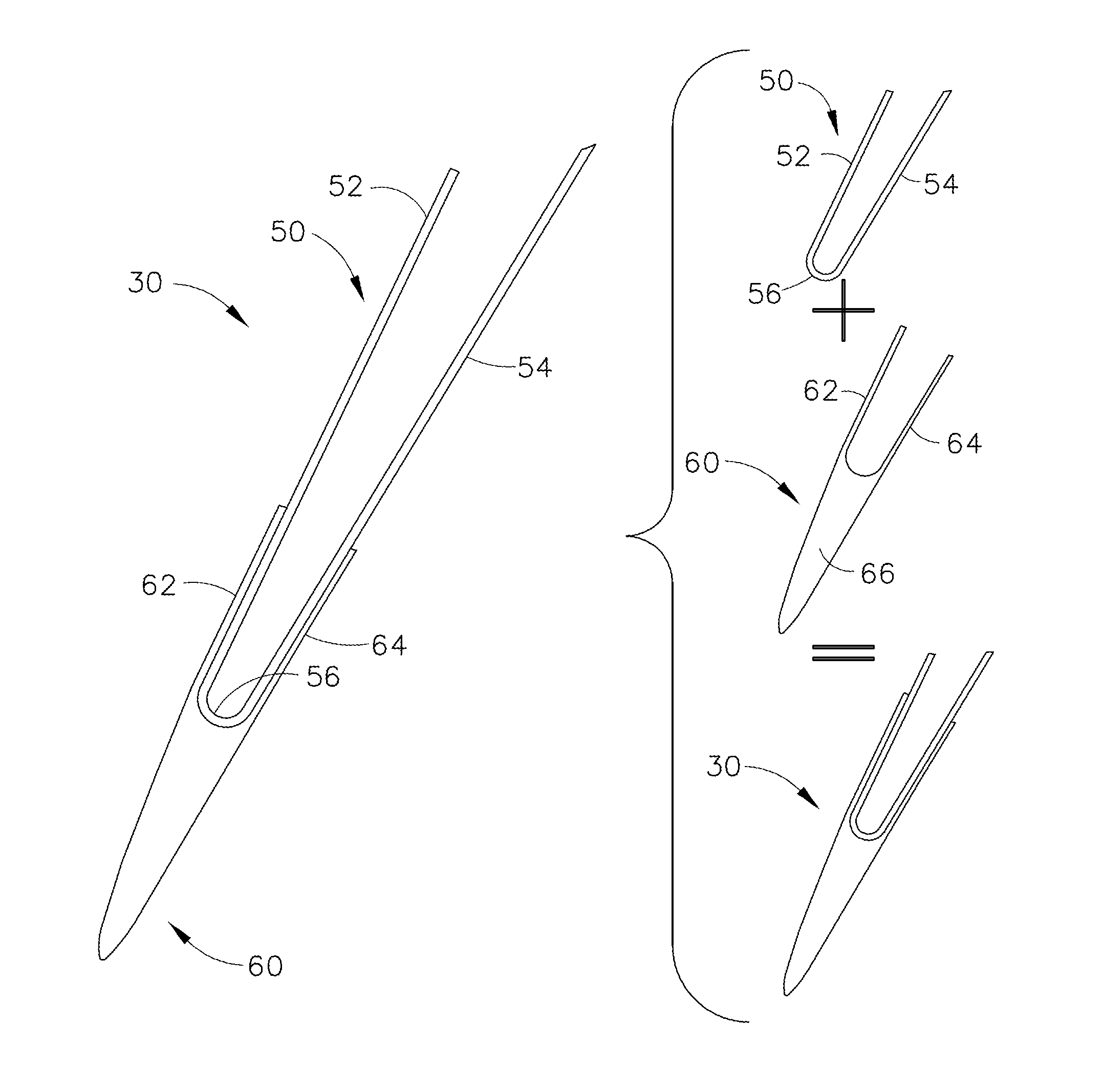
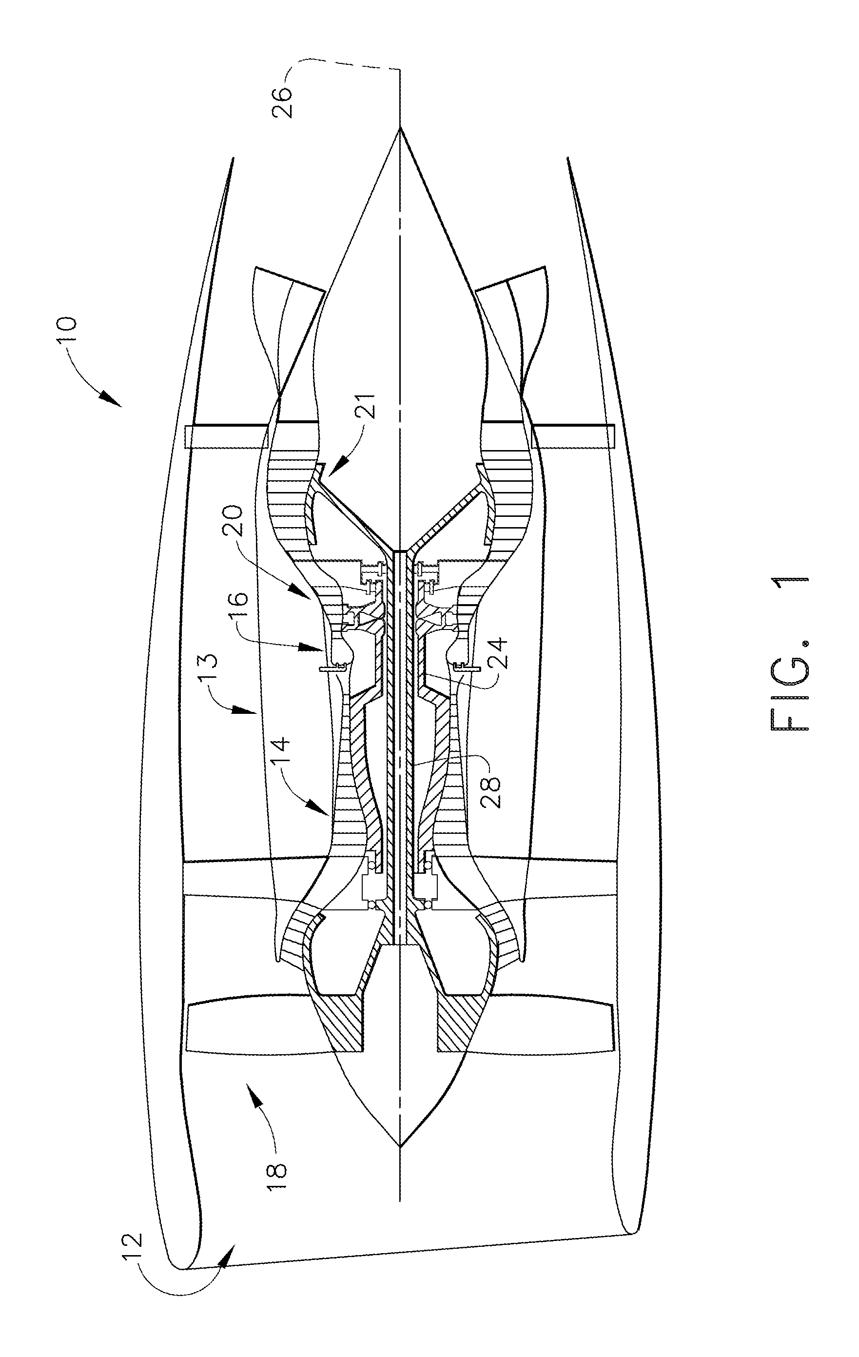
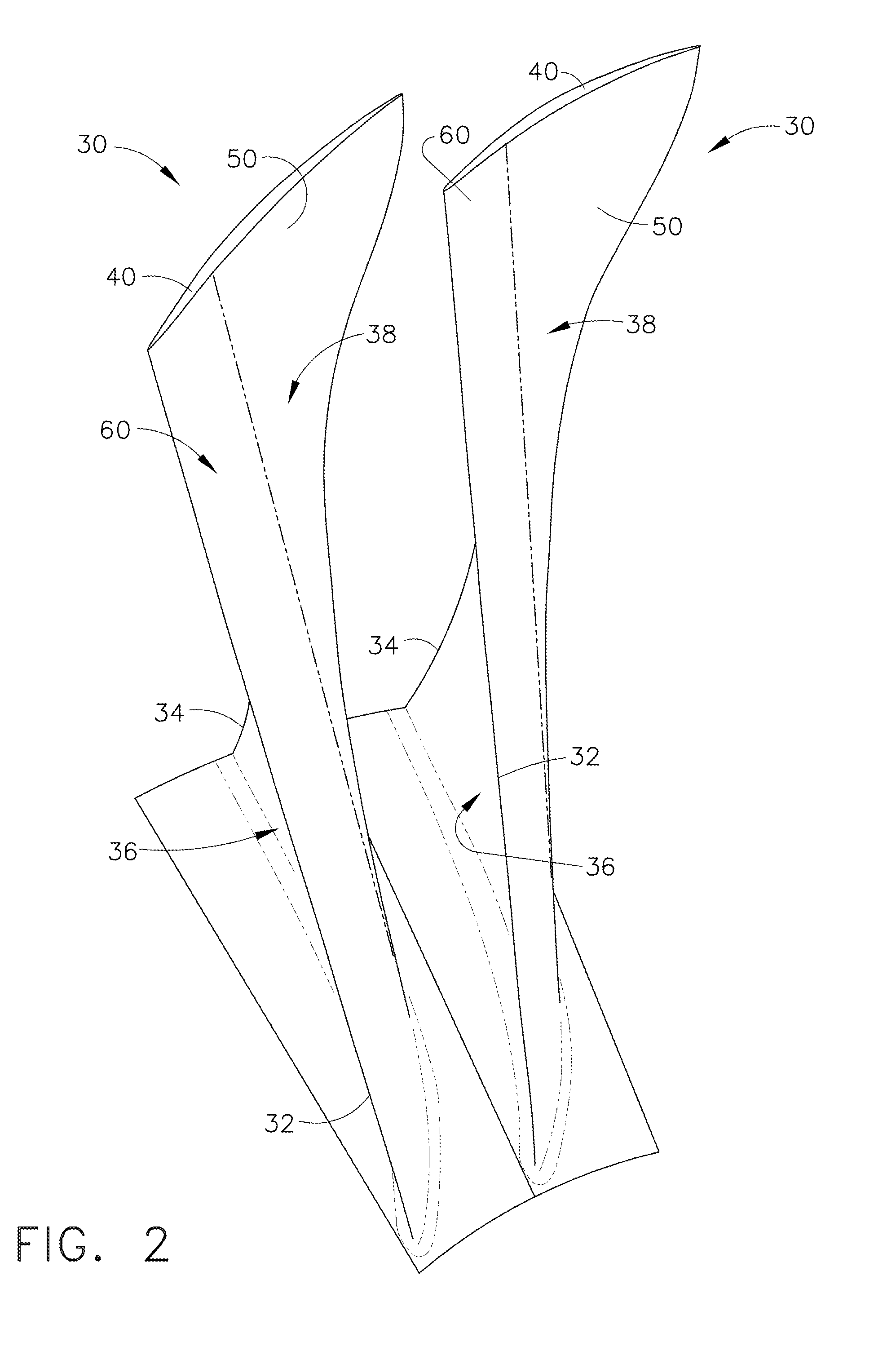
[0023]Referring to FIGS. 1-9 various embodiments of composite airfoils are depicted having a metal leading edge insert assembly. The composite airfoil may be utilized at various locations of a gas turbine engine including, but not limited to, a fan, a compressor and a ...


PUM

PropertyMeasurementUnit
pressureaaaaaaaaaa
densityaaaaaaaaaa
metallicaaaaaaaaaa

Abstract

An airfoil assembly (30) comprises a composite airfoil (40) having a leading edge (32) and a trailing edge (34), a pressure side (36) extending between the leading edge and the trailing edge, a suction side (38) extending between the leading edge and the trailing edge, opposite the leading edge, a metallic leading edge assembly (130) disposed over the composite air-foil, the metallic leading edge assembly including a high density base (50), the metallic leading edge assembly also including a nose (60) disposed over the base, an adhesive bond layer disposed between the composite airfoil and the metallic leading edge assembly.

Description

BACKGROUND[0001]Present embodiments relate generally to gas turbine engines. More specifically, but not by way of limitation, present embodiments relate to composite airfoils having a metal leading edge assembly to enhance impact capability of composite blades.[0002]A typical gas turbine engine generally possesses a forward end and an aft end with its several core or propulsion components positioned axially there between. An air inlet or intake is located at a forward end of the engine. Moving toward the aft end, in order, the intake is followed by a compressor, a combustion chamber, and a turbine. It will be readily apparent from those skilled in the art that additional components may also be included in the engine, such as, for example, low-pressure and high-pressure compressors, and low-pressure and high-pressure turbines. This, however, is not an exhaustive list.[0003]The compressor and turbine generally include rows of airfoils that are stacked axially in stages. Each stage inc...

Claims


Application Information

Patent Timeline
Patent Type & Authority Applications(United States)
IPC IPC(8): F01D5/28F01D5/14F01D9/04
CPCF01D5/28F01D9/041F01D5/147F05D2220/32F05D2300/174F05D2230/60F05D2300/133F05D2300/171F05D2230/23B23P15/04F01D5/282F01D5/288F04D29/324F05D2240/303Y02T50/60
Inventor KRAY, NICHOLAS JOSEPHLI, QIANGALBRECHT, JR., RICHARD W.
Owner GENERAL ELECTRIC CO
Why Eureka
Try Eureka