Electro acoustic diaphragm

Active Publication Date: 2016-01-14
GP ACCOUSTICS (UK) LIMITED
View PDF13 Cites 11 Cited by
  • Summary
  • Abstract
  • Description
  • Claims
  • Application Information

AI Technical Summary

Benefits of technology

[0017]The shape and configuration of the diaphragm is beneficial since, unlike conventional axisymmetric geometries, diaphragms in accordance with the invention do not rely on ‘hoop strength’ to provide the stiffness so it is possible to use non-axisymmetric geometries. For example, in another less simple manifestation the voice coil may be race track or elliptical. In this case the modulations are defined as perpendicular and tangential to the voice coil. A race track geometry is of particular use where a linear acoustic source is required. A further benefit of the new geometry is that, due to its smaller radii of curvature, it may be possible to use a thinner material while maintaining geometric stability during handling and manufacture.
[0018]Suitab

Problems solved by technology

Alternatively, the diaphragm could be driven via the protruding, shaped portion using a suitably shaped voice coil drive bobbin, particularly if the protrusions were small, although assemb

Method used


Image

  • Electro acoustic diaphragm
  • Electro acoustic diaphragm
  • Electro acoustic diaphragm

Examples


Embodiment Construction

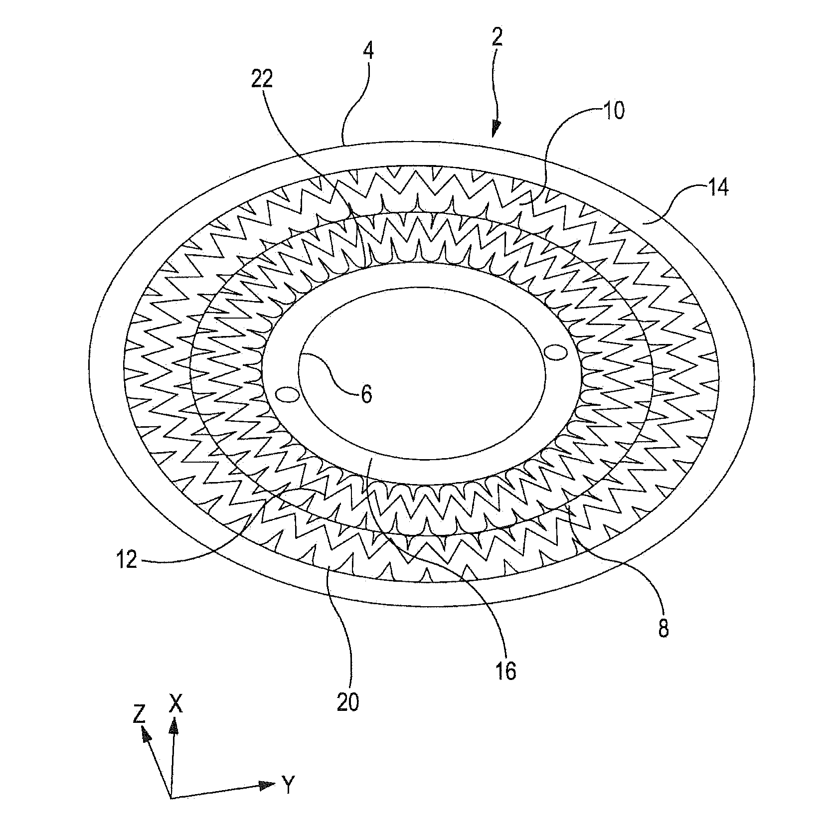
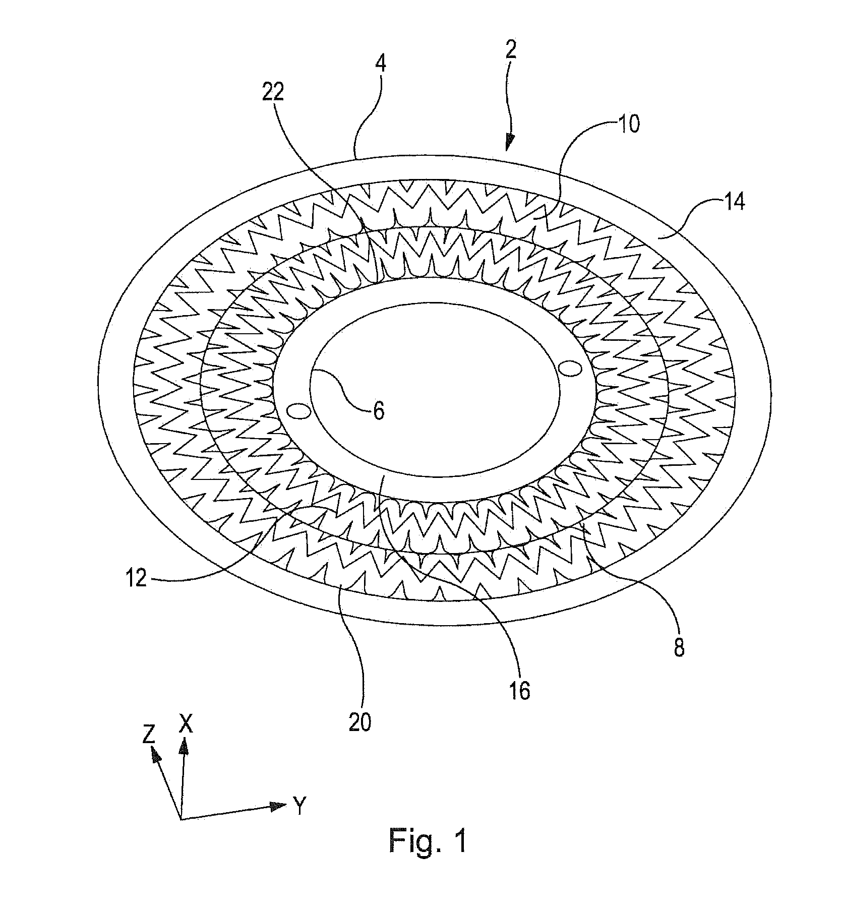
[0025]The diaphragm 2 shown in FIG. 1 lies generally in the Y-Z plane as illustrated, and is in the form of a thin ring, or annulus, with an outer circumferential edge 4 and an inner circumferential edge 6

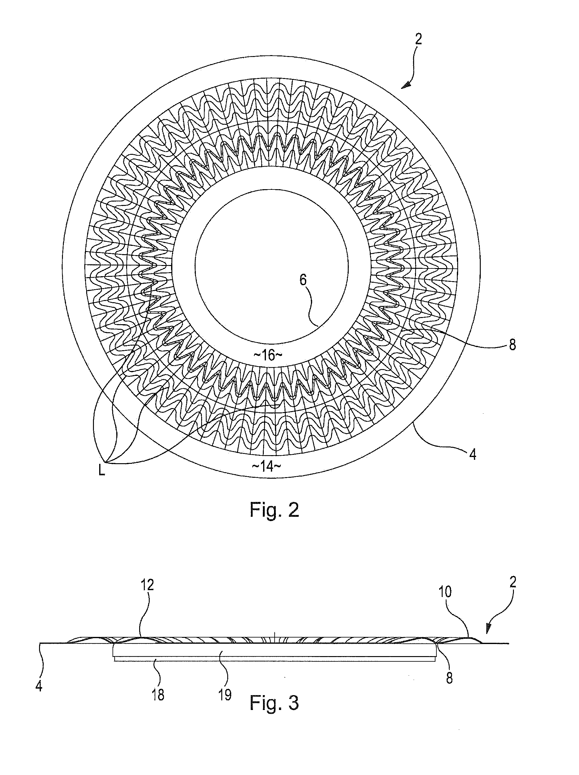
[0026]Between the outer and inner edges is a planar circumferential portion 8 to which, in use, a drive coil (not shown) would be attached and arranged to drive the diaphragm in the X direction so as to generate acoustic waves; again, any shape or configuration would suit this portion 8 provided the drive coil can be easily attached thereto, such as V-shaped, M-shaped or W-shaped in cross-section, though in practice a substantially planar form is most easily manufactured. This portion 8 is in the region of the glue joint fixing the diaphragm 2 to the drive coil bobbin (shown in FIG. 3).

[0027]Either side of the circumferential portion 8 are a series of smooth circumferential modulations, or convolutions, formed in the thin diaphragm, so as to protrude from the general plane of the d...


PUM


Abstract

A diaphragm for a loudspeaker, wherein the diaphragm is formed generally in a closed loop around a central void, the loop lying in a plane, the diaphragm having an axis in a direction orthogonal to the plane along which axis the diaphragm is arranged to be driven in use, the diaphragm having inner and outer circumferential edges which are adapted, in use, to be fixed in position, wherein a substantial portion of the diaphragm between the inner and outer edges is shaped in the direction of the said axis so as to protrude from the general plane of the diaphragm in either or both directions along the axis, and wherein said shaped portion when viewed along the direction of the axis comprises at least one series of curves extending radially across substantially all of the driven area of the diaphragm.

Description

FIELD OF THE INVENTION[0001]The present invention relates to a diaphragm for converting electrical signals into sound, such as a diaphragm for a compression driver loudspeaker, a direct radiating loudspeaker in the form of a closed loop, or a concentric drive loudspeaker.BACKGROUND ART[0002]In electro-acoustics there is a need for a system which simultaneously provides good quality high and low frequency bandwidths, whilst being relatively simple, robust, reliable and cheap. Maintaining the high frequency output of a compression driver requires a phase-plug closely spaced to the diaphragm to avoid an excessive acoustic compliance. The smaller this spacing the more extended the high frequency bandwidth will be. This phase plug to diaphragm spacing also limits the maximum diaphragm displacement since if the diaphragm contacts the phase plug gross distortion or even mechanical failure will occur. Since lower frequencies require larger volumes of air to be displaced, the smaller the pha...

Claims


Application Information

Patent Timeline
IPC IPC(8): H04R7/02
CPCH04R7/02H04R7/00H04R7/14H04R7/04
Inventor OCLEE-BROWN, JACK ANTHONYDODD, MARK ALEXANDER
Owner GP ACCOUSTICS (UK) LIMITED
Why Eureka
Try Eureka