A Supervised Autonomous Robotic System for Complex Surface Inspection and Processing

Active Publication Date: 2016-01-21
CARNEGIE MELLON UNIV
View PDF4 Cites 59 Cited by
  • Summary
  • Abstract
  • Description
  • Claims
  • Application Information

AI Technical Summary

Benefits of technology

[0007]The system disclosed herein precisely maneuvers one or more machine vision components and/or one or more surface processing devices over the surface of a three-dimensional object. The vision systems gather data about the surface that are used to inform the surface process. These data include both intrinsic properties of the surface, such as color, texture or abstract classification results, along with precise estimates of the distance and orientation of the surface relative to the processing point. These

Problems solved by technology

Some problems, such as exploratory mapping, operate on a dynamic environment with many unknowns.
Other problems, such as lawn mowing, operate on a quasi-static envi

Method used


Image

  • A Supervised Autonomous Robotic System for Complex Surface Inspection and Processing
  • A Supervised Autonomous Robotic System for Complex Surface Inspection and Processing
  • A Supervised Autonomous Robotic System for Complex Surface Inspection and Processing

Examples


Embodiment Construction

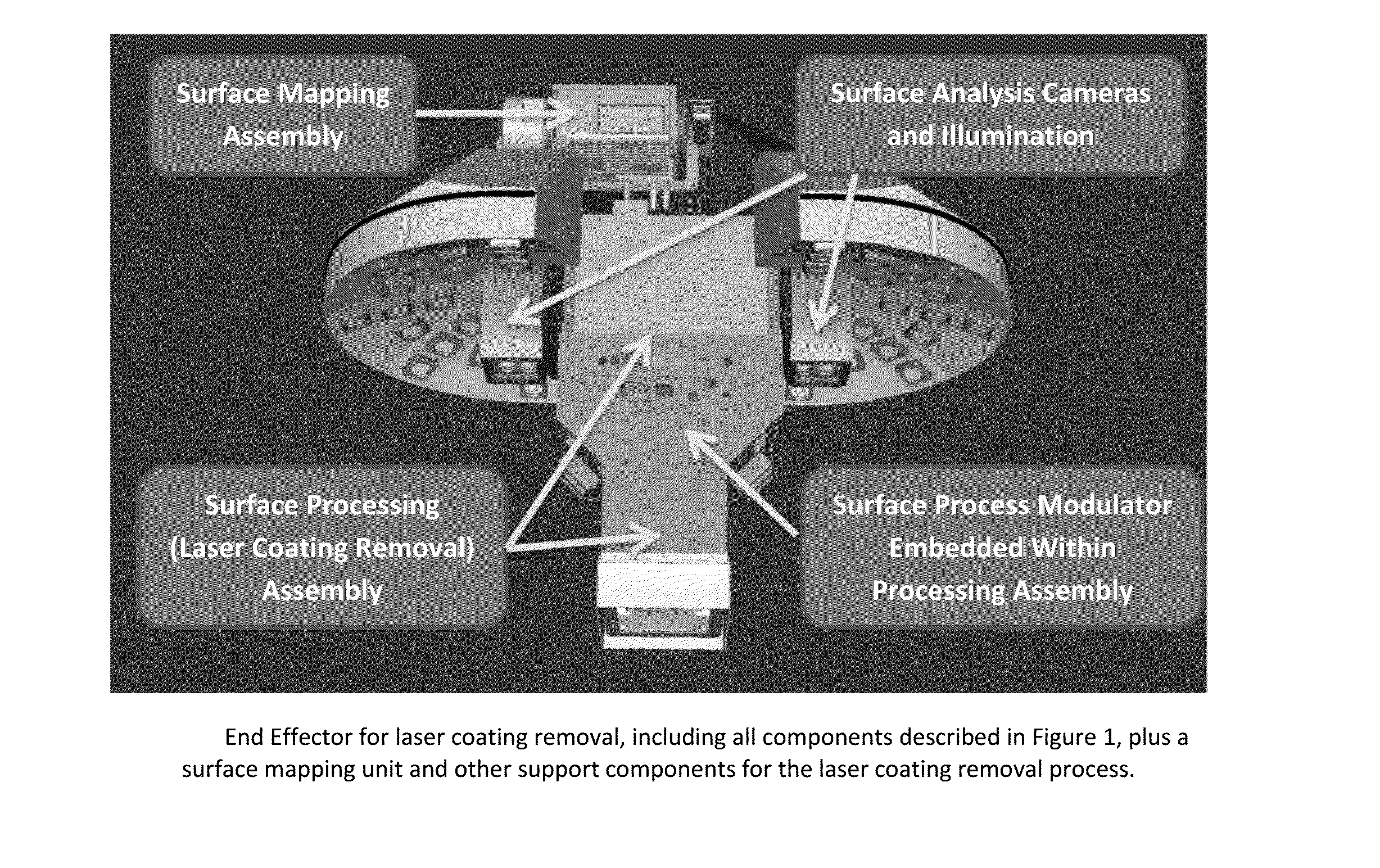
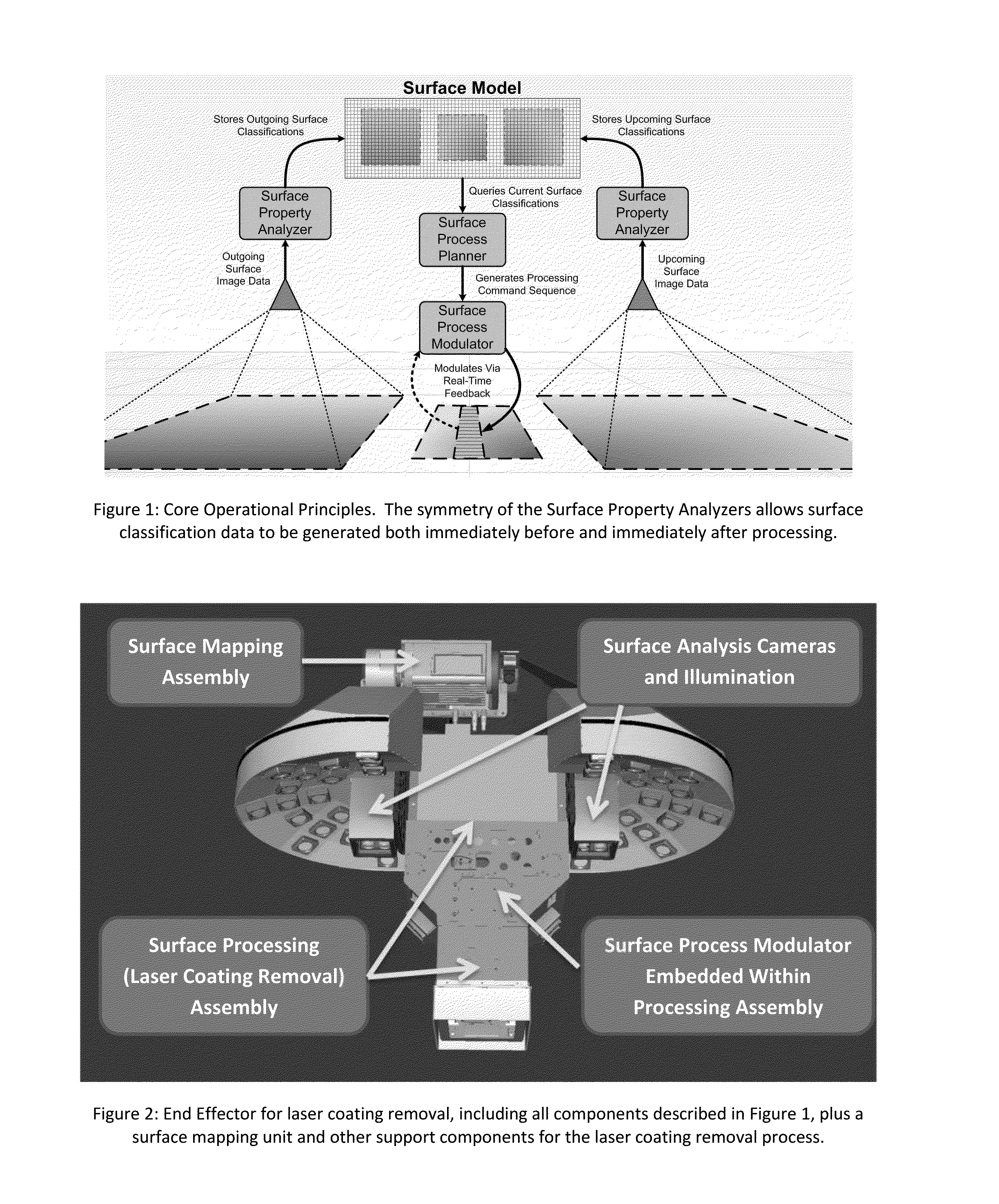
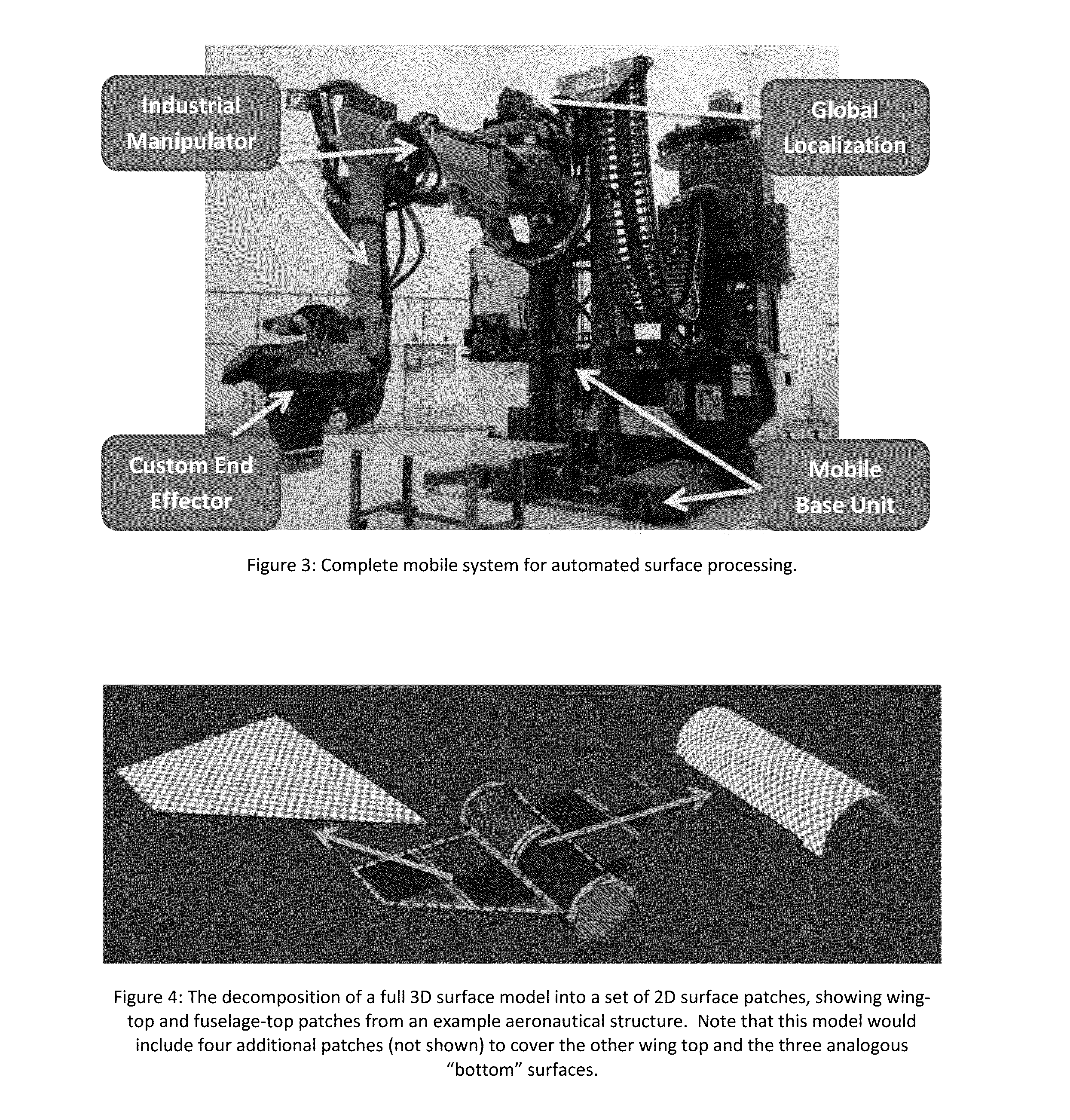
[0037]In one embodiment, the system can maneuver two machine vision components and a surface processing device over the surface of a three-dimensional object. The vision system is meant to gather sufficient data about the surface passing beneath the processing point to accurately plan for and modulate the surface process to efficiently generate high-quality results. In the case of the currently-implemented system, the surface processing device is, in one example, a high-power laser scanner, originally designed for laser welding, which is used to remove coatings from aeronautical surfaces, and the vision components estimate both the present state of the surface, i.e., where there remains coating to be stripped, and the distance and orientation of the surface relative to the aforementioned high-power laser scanner

[0038]The central use case of continuous surface processing is captured in FIG. 1, showing the principal collaborations between five critical system components and the target...


PUM


Abstract

The invention disclosed herein describes a supervised autonomy system designed to precisely model, inspect and process the surfaces of complex three-dimensional objects. The current application context for this system is laser coating removal of aircraft, but this invention is suitable for use in a wide variety of applications that require close, precise positioning and maneuvering of an inspection or processing tool over the entire surface of a physical object. For example, this system, in addition to laser coating removal, could also apply new coatings, perform fine-grained or gross inspection tasks, deliver and/or use manufacturing process tools or instruments, and/or verify the results of other manufacturing processes such as but not limited to welding, riveting, or the placement of various surface markings or fixtures.

Description

RELATED APPLICATIONS[0001]This application claims the benefit of U.S. Provisional Application No. 61 / 852,310, filed Mar. 15, 2013.GOVERNMENT INTEREST[0002]This invention was made partially with government support under the U.S. Air Force number FA5320-09-D-5601 & U.S. Army W91ZLK-10-D-0005 Task 0793. The government has certain rights in this invention.FIELD OF THE INVENTION[0003]This invention relates to the control of robotic manipulators to move a surface processing device over the surface of a three dimensional object. In particular, the present application has utility for removing paint from the surfaces of aircraft fuselage, wings and control surfaces.BACKGROUND OF THE INVENTION[0004]Scenarios which require a robot to process, visit, or in some way perform an action over the entirety of a given workspace are known as coverage problems. Common examples of coverage problems include lawn mowing, exploratory mapping, household vacuuming, surveillance, surface painting and de-painti...

Claims


Application Information

Patent Timeline
IPC IPC(8): B25J9/16
CPCB25J9/1671Y10S901/28Y10S901/41Y10S901/06G01B11/24G01N21/9515G05B2219/45071G05B2219/37449B25J9/1664B25J9/1697Y10S901/44Y10S901/47B23Q17/2233G05B19/4099
Inventor LAWRENCE, III, STUART EDWINBAKER, CHRISTOPHER LBAKER, CHRISTOPHER RANDOLPHGALATI, DAVID GHAINES, JUSTIN CHERMAN, HERMANKELLEY, ALONZO JMEYHOFER, ERICSTENTZ, ANTHONYVALOIS, JEAN-SEBASTIEN
Owner CARNEGIE MELLON UNIV
Why Eureka
Try Eureka