Non-contact discharge test method and device

a non-contact discharge and test method technology, applied in the direction of testing dielectric strength, using optic methods, instruments, etc., can solve the problems of difficult to secure a location (s) where a camera or a plurality of cameras are installed, catching fire and explosion of fuel stored in the wing, and quantitative evaluation of the energy of emitted light is theoretically difficul

Active Publication Date: 2016-01-21
NAT UNIV CORP KYUSHU INST OF TECH (JP)
View PDF2 Cites 9 Cited by
  • Summary
  • Abstract
  • Description
  • Claims
  • Application Information

AI Technical Summary

Benefits of technology

[0015]According to the present invention, for example, in a lightning resistance test for aircraft, a non-contact discharge test can be performed in a poor electromagnetic noise environment by detecting weak light emission and processing the intensity waveform of light emission of discharge or spark. As a result, the technique of detecting the discharge-or-spark induced light emission and evaluating its energy can be applied to an actual lightning resistance test for aircraft. Further, in addition to the image of emitted light and the light emission, an electromagnetic wave signal is obtained. Therefore, it is possible to instantaneously evaluate the time, location, and the magnitude of discharge (spark) without waiting for development of film or the like.

Problems solved by technology

In such a case, there arises a possibility that fuel stored in the wing catches fire and explodes.
Accordingly, it has been difficult to secure a location (s) where a camera or a plurality of cameras are installed.
Although the ISO sensitivity of film and the F value of lens are designated, the conventional method has problems; for example, quantitative evaluation of the energy of emitted light is theoretically difficult.
However, this method has a problem of unable to identify the location of any explosion.

Method used


Image

  • Non-contact discharge test method and device
  • Non-contact discharge test method and device
  • Non-contact discharge test method and device

Examples


example 1

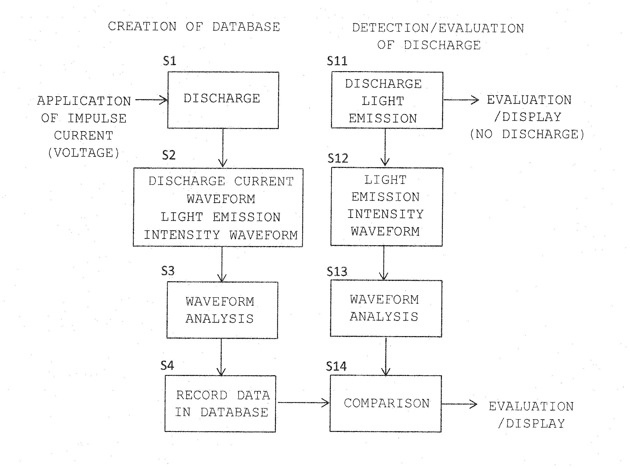
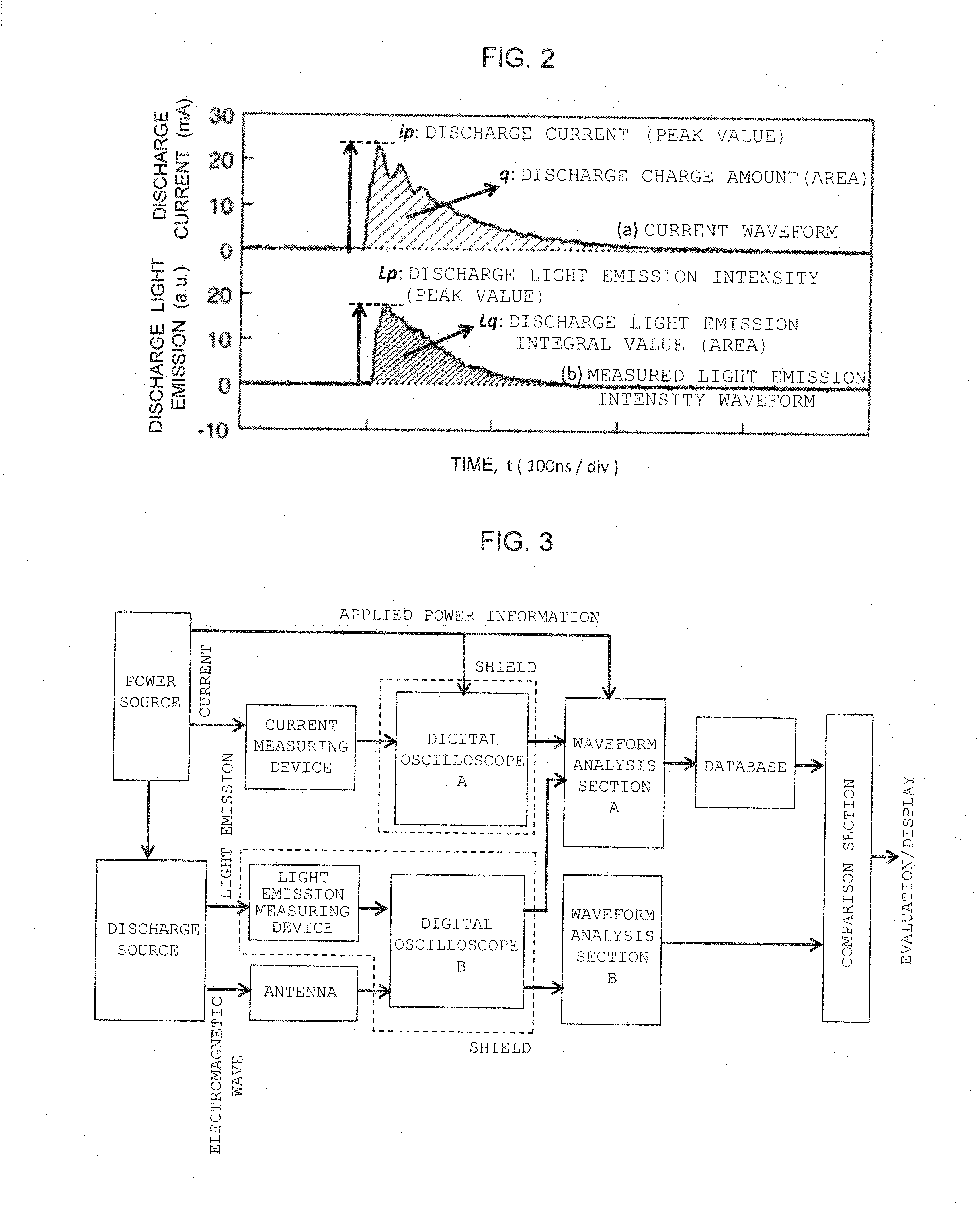
[0048]FIG. 9 is a schematic diagram showing an example in which the present invention is embodied as a lightning resistance test device. In a lightning resistance test, a current source LI_CG which can supply a lightning impulse current and a current detector CT for detecting the impulse current are used as a power source. In the case of the impulse power source, its polarity is known. However, it is necessary to know the timing at which discharge or spark has been generated. The timing is measured through use of an antenna A1.

[0049]In order to measure light emission of a sample (sample with a fastener F) of CFRP, the sample is placed in a dark box CF. In the dark boxy DB, a digital camera CAM for capturing an image of emitted light and an optical fiber OF for guiding a light emission signal to a photomultiplier tube PMT are properly disposed. The digital camera CAM is placed in a shield box S3. The optical fiber OF extends from the dark boxy DB to a point within a different shield ...


PUM


Abstract

In a non-contact discharge test performed in a poor electromagnetic noise environment, the energy of discharge is evaluated by detecting weak light emission and processing the intensity waveform of light emission of the discharge. A database is created by measuring the intensity waveform of light emission of discharge generated as a result of application of a voltage or current to a measurement object through use of a light emission measuring device, simultaneously measuring the current waveform of the discharge through use of a current measuring device, and storing in the database the relation between analysis data sets obtained through analysis of the waveforms on the basis of information of the voltage or current applied to the measurement object. The intensity waveform of the light emission of the discharge or spark generated from the measurement object is measured while an electromagnetic wave generated as a result of the discharge of the measurement object is used as a reference. The magnitude of the discharge is estimated as a value by comparing light emission data obtained through analysis of the intensity waveform with the data recorded in the database.

Description

[0001]This application claims the benefit of PCT International Application Number PCT / JP2013 / 083320 filed Dec. 12, 2013 and Japanese Application No. 2013-004497 filed, Jan. 15, 2013 in Japan, the disclosures of which are incorporated herein by reference.TECHNICAL FIELD[0002]The present invention relates to a non-contact discharge test method and a non-contact discharge test device which evaluate, in a non-contact state, discharge or spark of a measurement object by optically measuring a phenomenon of light emission due to the discharge or spark.BACKGROUND ART[0003]In the case of a new aircraft in which CFRP (carbon fiber reinforced plastic) is used for the main wings and / or airframe structure, if a main wing is struck by lightning, discharge (=voltage spark) or spark (=thermal spark or arc) may be generated at a fastener (a fastening bolt made of metal) attached to the main wing of CFRP. In such a case, there arises a possibility that fuel stored in the wing catches fire and explode...

Claims


Application Information

Patent Timeline
Patent Type & Authority Applications(United States)
IPC IPC(8): G01R31/12G01R31/50
CPCG01R31/025G01R31/1218G01R31/008G01R31/50
Inventor OHTSUKA, SHINYAYAMAGUCHI, YUKITSUBATA, HIROYUKI
Owner NAT UNIV CORP KYUSHU INST OF TECH (JP)
Why Eureka
Try Eureka