Quantum Imaging for Underwater Arctic Navigation

a technology of arctic navigation and quantitative imaging, applied in special purpose vessels, instruments, distance measurement, etc., can solve the problems of increasing the risk of detection, unable to penetrate water, and difficult safety navigation of underwater vehicles

Active Publication Date: 2016-01-21
UNITED STATES OF AMERICA
View PDF3 Cites 21 Cited by
  • Summary
  • Abstract
  • Description
  • Claims
  • Application Information

AI Technical Summary

Benefits of technology

[0020]The system may further comprise a gravity sensor module configured to obtain location information by measuring a local gravitational field; an inertial navigation module configured to obtain location information from any of a gyro, compass, accelerometer, and dead reckoning systems; a global positioning system (GPS) module configured to obtain location information from GPS satellites; and a sonar ...

Problems solved by technology

The stealthy navigation of underwater vehicles is a very challenging problem.
Indeed, radio-frequencies and GPS signals are generally unable to penetrate water.
Similarly, astronomical navigation using the position of the stars typically requires the vehicle to travel close to the surface of the sea, increasing the risk of detection.
The problem of underwater navigation is compounded if the vehicle is located in high latitudes; e.g., near the North Pole.
In this situation, gyroscopes and compasses become unreliable and lead to big errors in the dead reckoning estimations made by the inertial navigation system.
Further challenges emerge if the vehicle is traveling under the Arctic ice shelf.
Indeed, temperature variations and the eff...

Method used


Image

  • Quantum Imaging for Underwater Arctic Navigation
  • Quantum Imaging for Underwater Arctic Navigation
  • Quantum Imaging for Underwater Arctic Navigation

Examples


Embodiment Construction

[0040]The embodiments herein and the various features and advantageous details thereof are explained more fully with reference to the non-limiting embodiments that are illustrated in the accompanying drawings and detailed in the following description. Descriptions of well-known components and processing techniques are omitted so as to not unnecessarily obscure the embodiments herein. The examples used herein are intended merely to facilitate an understanding of ways in which the embodiments herein may be practiced and to further enable those of skill in the art to practice the embodiments herein. Accordingly, the examples should not be construed as limiting the scope of the embodiments herein.

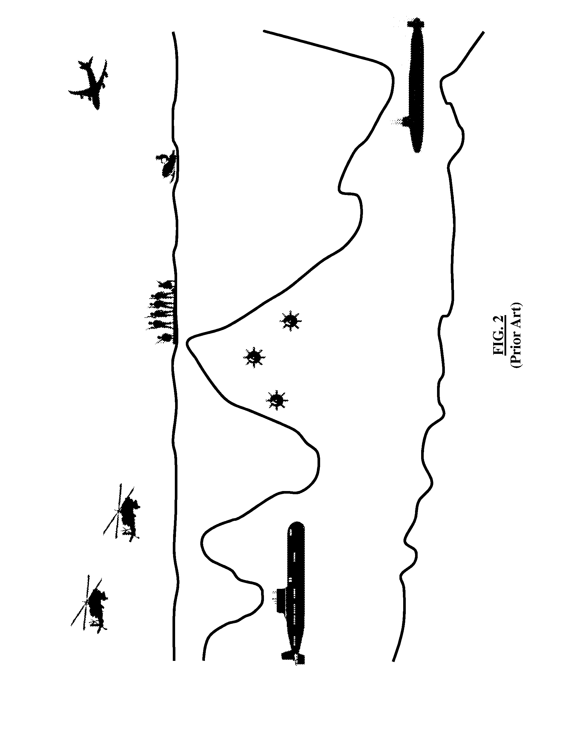
[0041]As generally described above, the precise navigation of underwater vehicles is a difficult task due to the challenges imposed by the variable oceanic environment. It is particularly difficult if the underwater vehicle is trying to navigate under the Arctic ice shelf. Indeed, in this scena...


PUM


Abstract

A quantum photonic imaging device used in an underwater vehicle for stealthy detection of underwater objects includes a photon generating module that generates an entangled pair of photons that includes a signal photon and an ancilla photon, wherein the ancilla photon is retained within the device; a transmitter that transmits the signal photon towards a region of space for detecting an underwater object; a receiver that detects an incoming photon to the device; and a correlation module that distinguishes the signal photon that is reflected back to the receiver due to a presence of the object from environmental noise photons, wherein the distinguishing includes determining an entanglement correlation of the detected photon with the ancilla photon, and wherein a presence of the entanglement correlation between the detected photon and the ancilla photon indicates that the detected photon is the signal photon reflected back from the object.

Description

GOVERNMENT INTEREST[0001]The embodiments described herein may be manufactured, used, and / or licensed by or for the United States Government without the payment of royalties thereon.BACKGROUND[0002]1. Technical Field[0003]The embodiments herein relate to quantum information science (QIS), and more particularly to QIS used for underwater imaging and navigation.[0004]2. Description of the Related Art[0005]A major scientific thrust from recent years has been to try to harness quantum phenomena to increase the performance of a wide variety of information processing devices. QIS has emerged as a scientific undertaking that promises to revolutionize our information infrastructure. In particular, QIS offers the possibility of quantum sensors. That is, sensing devices that exploit quantum phenomena in such a way that they perform much better than their classical counterparts. Some examples of quantum sensing devices with a clear military application include radar, magnetometers, and gravimet...

Claims


Application Information

Patent Timeline
IPC IPC(8): G01S17/89B63G8/00G01C21/20G01S17/04G01S17/08G01S17/86G01S17/87G01S17/93G01S19/14
CPCG01S17/89G01S17/08B63G8/00G01S19/14G01S17/93G01C21/20G01S17/87G01S7/493G01S15/08B63C11/48B63G8/001B63G8/28G01S19/18G01S17/04G01S17/86
Inventor LANZAGORTA, MARCO
Owner UNITED STATES OF AMERICA
Why Eureka
Try Eureka