Electrode, power storage device, electronic device, and vehicle

a technology of power storage device and power storage device, which is applied in the direction of battery, wound/folded electrode electrode, sustainable manufacturing/processing, etc., can solve the problems of promoting deterioration of power storage device, and achieve excellent cycle characteristics, high charge and discharge efficiency, and high capacitance

Active Publication Date: 2016-01-21
SEMICON ENERGY LAB CO LTD
View PDF0 Cites 12 Cited by
  • Summary
  • Abstract
  • Description
  • Claims
  • Application Information

AI Technical Summary

Benefits of technology

[0009]An object of one embodiment of the present invention is to provide a power storage device having high capacitance. Another object of one embodiment of the present invention is to provide a power storage device with excellent cycle characteristics. Another object of one embodiment of the present invention is to provide a power storage device with high charge and discharge efficiency. An object of one embodiment of the present invention is to provide a long-life power storage device.

Problems solved by technology

In this case, the power storage device is bent with the flexible portion, so that repeated change in the form of the power storage device might cause separation between a current collector and an active material in the power storage device.
As a result, deterioration of the power storage device might be promoted.

Method used


Image

  • Electrode, power storage device, electronic device, and vehicle
  • Electrode, power storage device, electronic device, and vehicle
  • Electrode, power storage device, electronic device, and vehicle

Examples


embodiment 1

[0058]In this embodiment, a negative electrode included in a power storage device is described.

[0059]An example of power storage devices includes a lithium-ion secondary battery. In the lithium-ion secondary battery, in the case where a material that is alloyed and dealloyed with lithium is used as a negative electrode active material, the capacity of the power storage device can be increased compared with the case where graphite is used as a negative electrode active material. For example, when graphite is used as a negative electrode active material, the theoretical capacity is 372 mAh / g. On the other hand, when silicon, which is a material that is alloyed and dealloyed with lithium, is used as a negative electrode active material, the theoretical capacity is 4200 mAh / g, which is over ten times as much as that of graphite.

[0060]However, a material that is alloyed and dealloyed with lithium (e.g., silicon) greatly expands and contracts with reception and release of carrier ions in ...

embodiment 2

[0109]In this embodiment, an example of a power storage device using the electrode shown in Embodiment 1 is described.

[Thin Storage Battery]

[0110]FIG. 4 and FIGS. 5A and 5B illustrate thin storage batteries as examples of power storage devices. When a flexible thin storage battery is used in an electronic device at least part of which is flexible, the storage battery can be bent as the electronic device is bent.

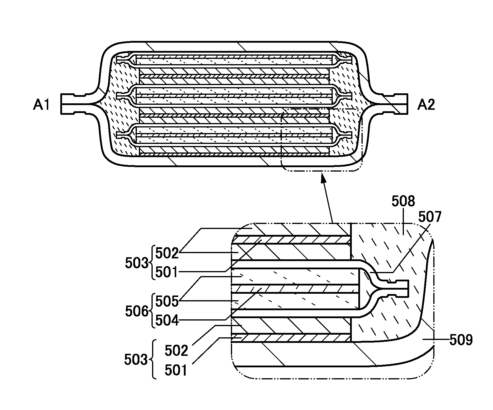
[0111]FIG. 4 illustrates the appearance of a thin storage battery 500. FIG. 5A is a cross-sectional view taken along dashed-dotted line A1-A2 in FIG. 4, and FIG. 5B is a cross-sectional view taken along dashed-dotted line B1-B2 in FIG. 4. The thin storage battery 500 includes a positive electrode 503 including a positive electrode current collector 501 and a positive electrode active material layer 502, a negative electrode 506 including a negative electrode current collector 504 and a negative electrode active material layer 505, a separator 507, an electrolytic solution 508...

embodiment 3

[0234]In this embodiment, examples of an electronic device including the above power storage device will be described.

[0235]Examples of electric devices include the following: display devices such as televisions and monitors, lighting devices, desktop or laptop personal computers, word processors, image reproduction devices which reproduce still images or moving images stored in recording media such as digital versatile discs (DVDs), portable or stationary audio reproduction devices such as compact disc (CD) players and digital audio players, portable or stationary radio receivers, audio recording and reproducing devices such as tape recorders and IC recorders (voice recorders), headphone, stereos, remote controllers, clocks such as table clocks and wall clocks, cordless phone handsets, transceivers, cellular phones, car phones, portable or stationary game machines, pedometers, calculators, portable information terminals, electronic notebooks, e-book readers, electronic translators,...


PUM

PropertyMeasurementUnit
thicknessaaaaaaaaaa
thicknessaaaaaaaaaa
thicknessaaaaaaaaaa

Abstract

A power storage device with high capacity is provided. Alternatively, a power storage device with excellent cycle characteristics is provided. Alternatively, a power storage device with high charge and discharge efficiency is provided. Alternatively, a power storage device with a long lifetime is provided. A negative electrode active material is provided over a negative electrode current collector, and the negative electrode active material layer is formed in such a manner that first layers and second layers are alternately stacked. The first layer includes at least an element selected from Si, Mg, Ca, Ga, Al, Ge, Sn, Pb, Sb, Bi, Ag, Zn, Cd, As, Hg, and In. The second layer includes oxygen and the same element as the one included in the first layer.

Description

BACKGROUND OF THE INVENTION[0001]1. Field of the Invention[0002]The present invention relates to an object, a method, or a manufacturing method. In addition, the present invention relates to a process, a machine, manufacture, or a composition of matter. In particular, one embodiment of the present invention relates to a semiconductor device, a display device, a light-emitting device, a power storage device, a storage device, a driving method thereof, or a manufacturing method thereof. In particular, one embodiment of the present invention relates to a power storage device and a manufacturing method thereof.[0003]2. Description of the Related Art[0004]In recent years, a variety of power storage devices; for example, secondary batteries such as lithium-ion secondary batteries, lithium-ion capacitors, and air cells, have been actively developed. In particular, demand for lithium-ion secondary batteries with high output and high energy density has rapidly grown with the development of t...

Claims


Application Information

Patent Timeline
Patent Type & Authority Applications(United States)
IPC IPC(8): H01M4/02H01G9/042H01M4/13H01M4/131H01M4/134H01M4/136H01M4/48H01M10/0525
CPCH01G9/042H01M10/0525H01M4/134H01M2220/20H01M4/136H01M2220/30H01M4/131H01M4/0428H01M4/13H01M4/133H01M4/139H01M4/366H01M4/386H01M4/5825H01M4/587H01M10/0427H01M10/0431H01M10/0436H01M10/052H01M10/058H01M10/0585H01M10/425H01G11/30Y02E60/10Y02P70/50Y02T10/70Y02E60/13
Inventor INOUE, NOBUHIROTAJIMA, RYOTAKURIKI, KAZUTAKAICHIJO, MITSUHIROHIURA, YOSHIKAZUSUGIKAWA, MAI
Owner SEMICON ENERGY LAB CO LTD
Why Eureka
Try Eureka