
Method and device for image and video transmission over low-bandwidth and high-latency transmission channels

a transmission channel and low-bandwidth technology, applied in selective content distribution, eavesdropping prevention circuits, instruments, etc., can solve the problems of severe image degradation, low overall image/video quality, etc., to reduce bandwidth, reduce priority, and increase the compression ratio of images

Inactive Publication Date: 2016-01-21
BARCO NV
View PDF2 Cites 3 Cited by
  • Summary
  • Abstract
  • Description
  • Claims
  • Application Information

AI Technical Summary

Benefits of technology

The present invention provides a solution to improve the transmission of high-quality or medical images and videos over bandwidth-limited networks. It offers methods to improve image quality, reduce latency, improve security and priority signalling, make maximum use of available computing power, and reduce power consumption for portable battery-operated devices. The patent also includes a classification algorithm that prioritizes image and video encoding algorithms for devices with lower priority, increasing the compression ratio for these areas in case of decreasing bandwidth. Overall, the invention improves the overall quality and efficiency of image and video transmission over network environments.

Problems solved by technology

Such problems are e.g., but not limited thereto, low overall image / video quality when only a low bandwidth channel is available, severe image degradation due to introduction of bit errors on the channel and the problem of latency when communication is bidirectional.

Method used


Image

  • Method and device for image and video transmission over low-bandwidth and high-latency transmission channels
  • Method and device for image and video transmission over low-bandwidth and high-latency transmission channels
  • Method and device for image and video transmission over low-bandwidth and high-latency transmission channels

Examples


Embodiment Construction

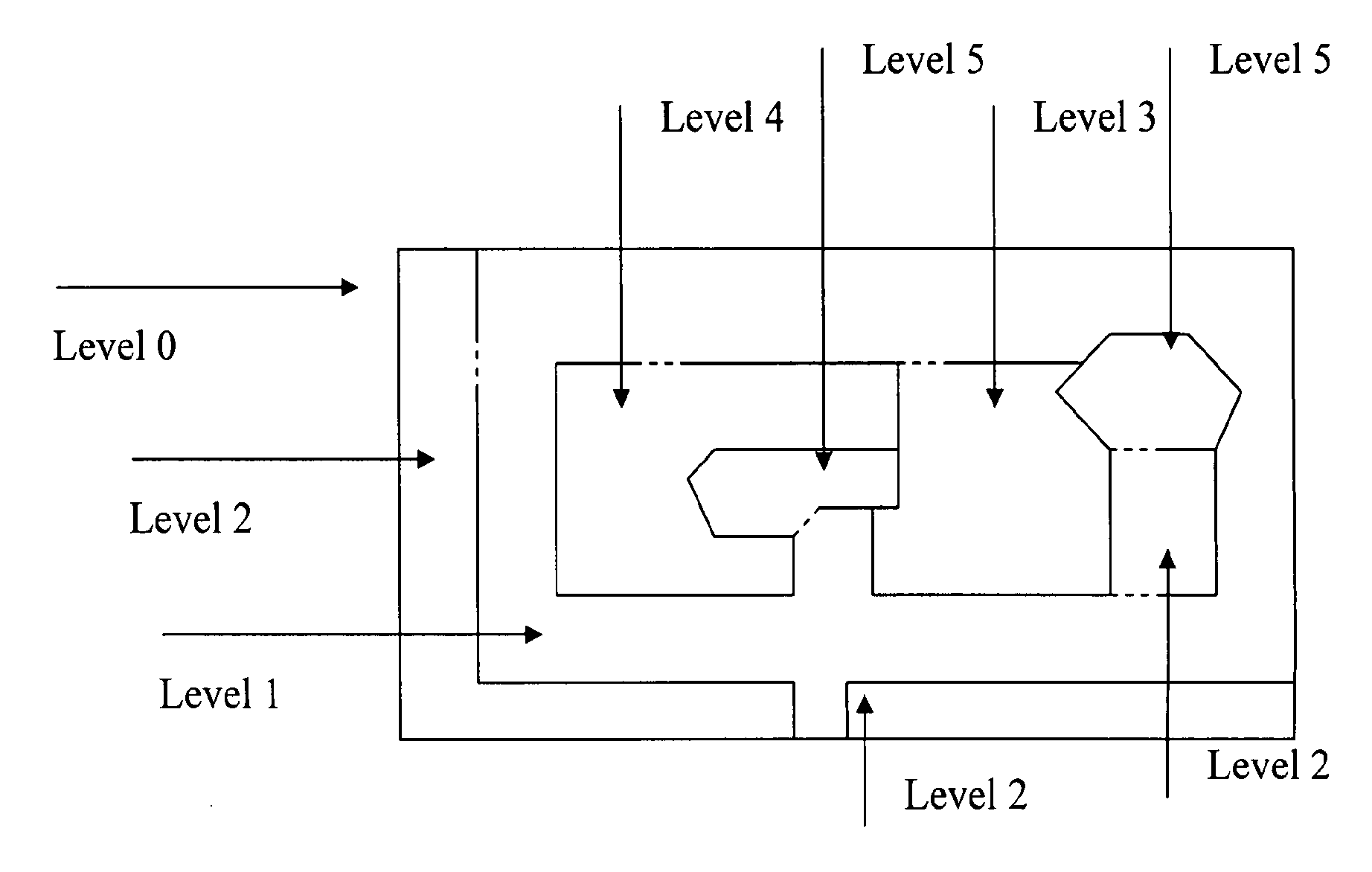
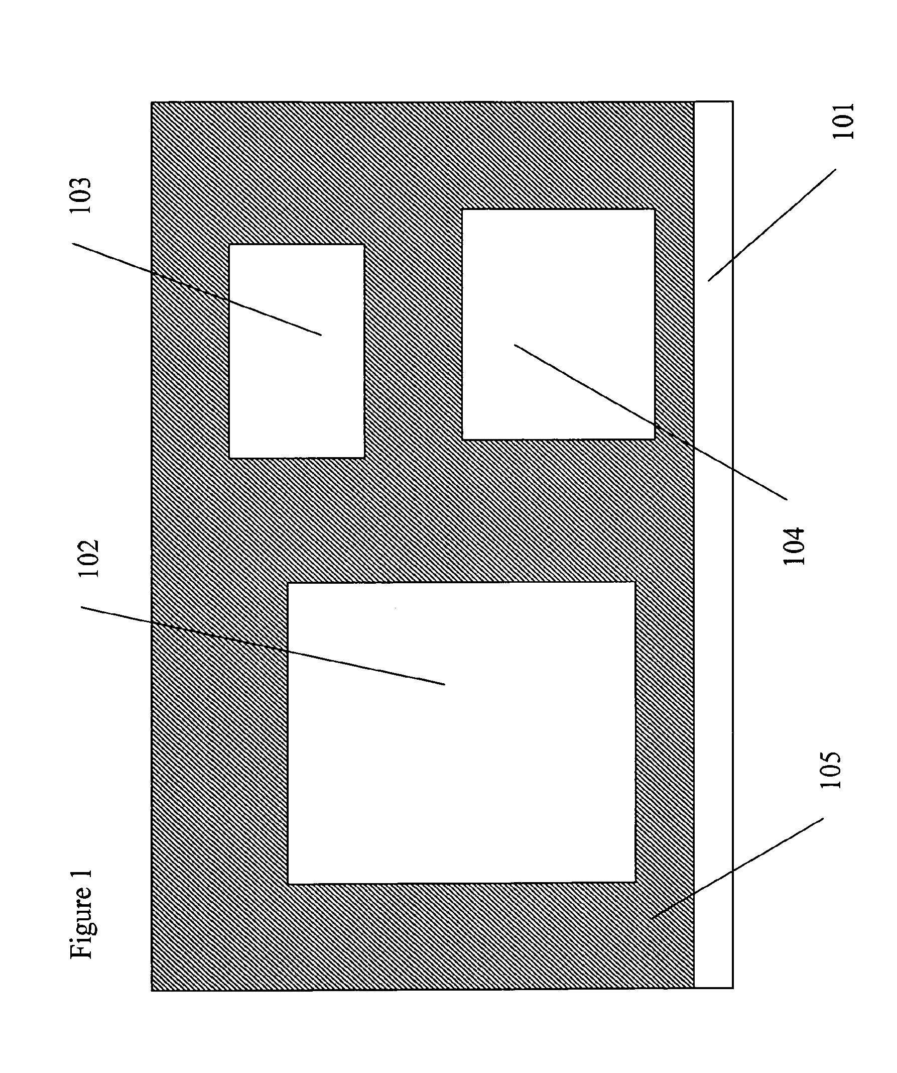
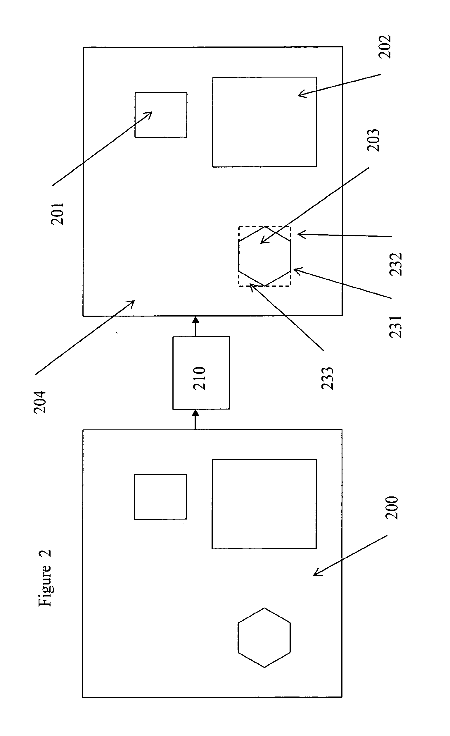
[0058]According to a first aspect of the present invention, a method and system are disclosed that allow for higher overall image quality compared to existing methods, when only a limited bandwidth is available. This is achieved by decomposing the image / video to be transmitted into multiple spatial areas, each having a specific image type, and detecting the image type of each of those areas and selecting the optimal image / video codec for those areas. Selecting the optimal image codec could mean optimizing on image quality (PSNR, MSE), optimising on compression ratio, optimizing on latency of the encoding / decoding process, optimizing to subjective image quality based on a model of the human vision system . . . . Decomposing the image / video could mean splitting the image / video stream into rectangular areas, each area having a specific image type. For example: if the desktop of a PC is to be replicated somewhere else then the desktop contents will have to be transmitted over a channel ...


PUM


Abstract

A method for transmission of images and / or video over bandwidth limited transmission channels having varying available bandwidth, which uses a classification algorithm to decompose the images and / or video to be transmitted into multiple spatial areas, each area having a specific image type; detecting the image type of each of those areas; and separately selecting for each of those areas an image and / or video encoding algorithm having a compression ratio. The classification algorithm is used to prioritize each of the areas, increase the compression ratio of the image and / or video encoding algorithm dedicated to spatial areas having lower priority in case of decreasing bandwidth.

Description

TECHNICAL FIELD OF THE INVENTION[0001]The present invention relates to systems and methods for transmission of high quality images and video over (wireless) bandwidth limited, lossy and high-latency transmission channels. With “high quality images and video” is typically meant “medical images and video”. More particularly, the invention relates to systems and methods for transmitting images and video over channels such as Wifi, UWB, Bluetooth, DECT, ZigBee, . . . and provides solutions for typical problems such as overall low image quality at higher compression ratio and high latency.BACKGROUND OF THE INVENTION[0002]This invention is in the field of methods and systems for transmitting images or video over channels where there is a bandwidth limitation present, where the channel possibly is lossy or where latency is important. The general problem to solve is the transport of high-quality images or video from one point to another. Because of the bandwidth limitations of the channel u...

Claims


Application Information

Patent Timeline
Patent Type & Authority Applications(United States)
IPC IPC(8): H04W12/02H04W4/30
CPCH04W12/02H04W4/04H04W4/026G06F21/6245H04N21/25841H04N21/25858H04N19/172H04N19/61H04N19/37H04N19/12H04N19/127H04N19/132H04N19/154H04N19/164H04N19/17H04N19/20H04N19/423H04N19/90H04W4/30H04W12/033H04W12/63H04W12/64H04L67/01H04L67/568
Inventor KIMPE, TOM
Owner BARCO NV
Learn More