Protective Sleeve With Bonded Wire Filaments and Methods of Construction Thereof

a protective sleeve and bonded wire technology, applied in the direction of insulation conductors/cables, cables, knitting, etc., can solve the problems of electrostatic discharge, esd, radio frequency interference, emi, etc., to achieve the effect of other than as desired, affecting the performance of control modules or other components in the vehicle, and affecting the proper functioning of electronic components

Active Publication Date: 2016-01-21
FEDERAL MOGUL POWERTAIN LLC
View PDF0 Cites 21 Cited by
  • Summary
  • Abstract
  • Description
  • Claims
  • Application Information

AI Technical Summary

Problems solved by technology

It is known that electromagnetic interference (EMI), radio frequency interference (RFI), and electrostatic discharge (ESD) pose a potential problem to the proper functioning of electronic components caused by interference due to inductive coupling between nearby electrical conductors and propagating electromagnetic waves.
For example, electrical currents in conductors associated with an electrical power system in an automobile may induce spurious signals in various electronic components, such as an electronic module which controls the functioning of the engine.
Such interference could downgrade the performance of control modules or other components in the vehicle, thereby causing the vehicle to act other than as desired.
Similarly, inductive coupling between electrical wiring and the lines carrying data in a computer network or other communication system may have a corrupting effect on the data being transmitted over the network.
While RFI, EMI, and ESD sleeves constructed as described above can be generally effective at eliminating electrical interference, the sleeves can be relatively expensive in manufacture, particularly when expensive coatings, such as silver, are used, and can exhibit some inefficiency in establishing and maintaining conductive connections between the conductive fiber constituents.
In addition, the conductive coating can be worn off, thereby impacting the ability of the sleeving to provide and maintain RFI, EMI, and / or ESD protection.
Further, the hybrid yarns tend to shift relative to one another upon being interlaced, thereby potentially negatively impacting the ability to provide and maintain maximum shielding against EMI, RFI and / or ESD.
The shifting has a negative impact as a result of the wires moving from their intended location, which tends to form enlarged openings between the wires, wherein the enlarged openings degrade the EMI, RFI, ESD shielding performance of the sleeve.

Method used


Image

  • Protective Sleeve With Bonded Wire Filaments and Methods of Construction Thereof
  • Protective Sleeve With Bonded Wire Filaments and Methods of Construction Thereof
  • Protective Sleeve With Bonded Wire Filaments and Methods of Construction Thereof

Examples


Embodiment Construction

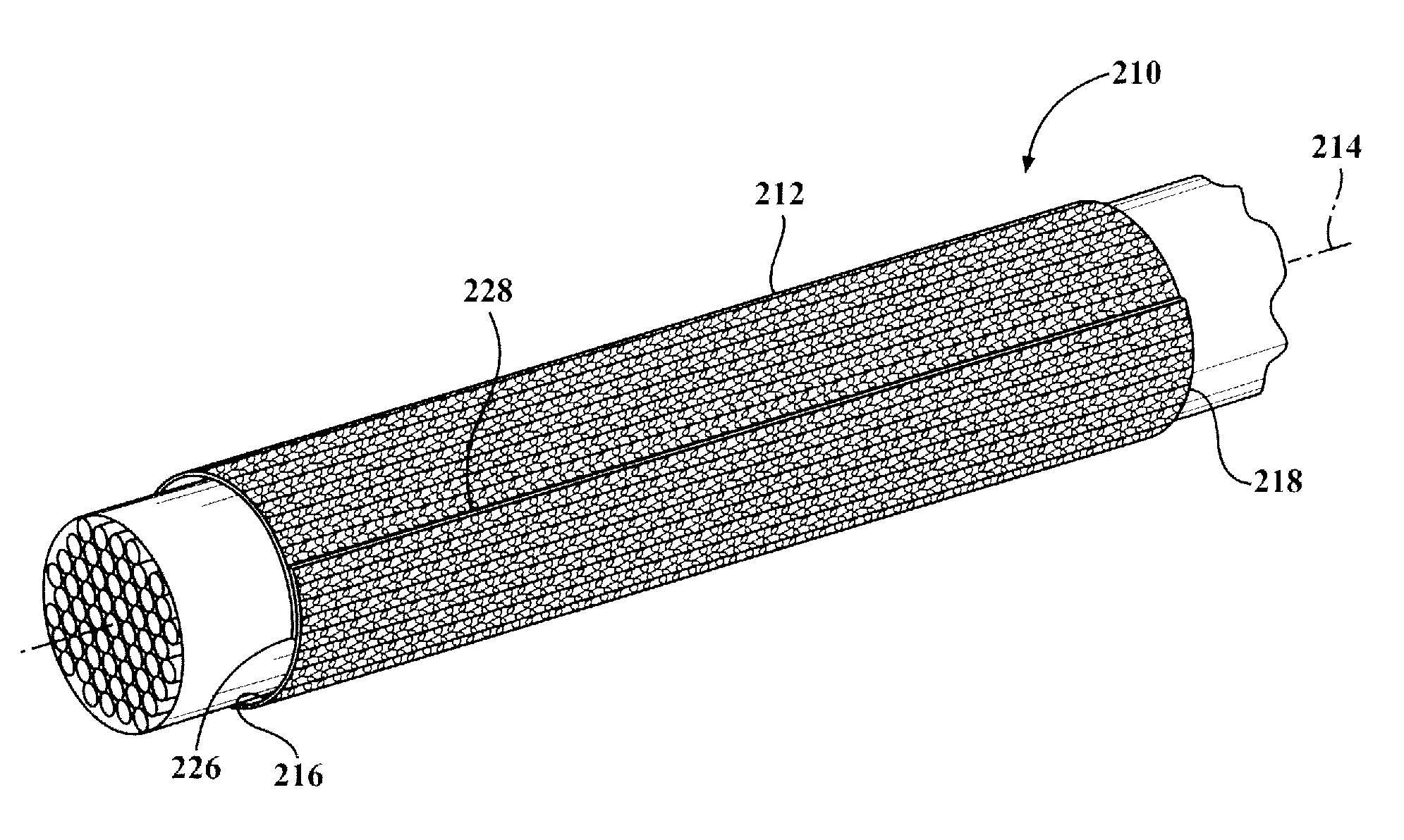
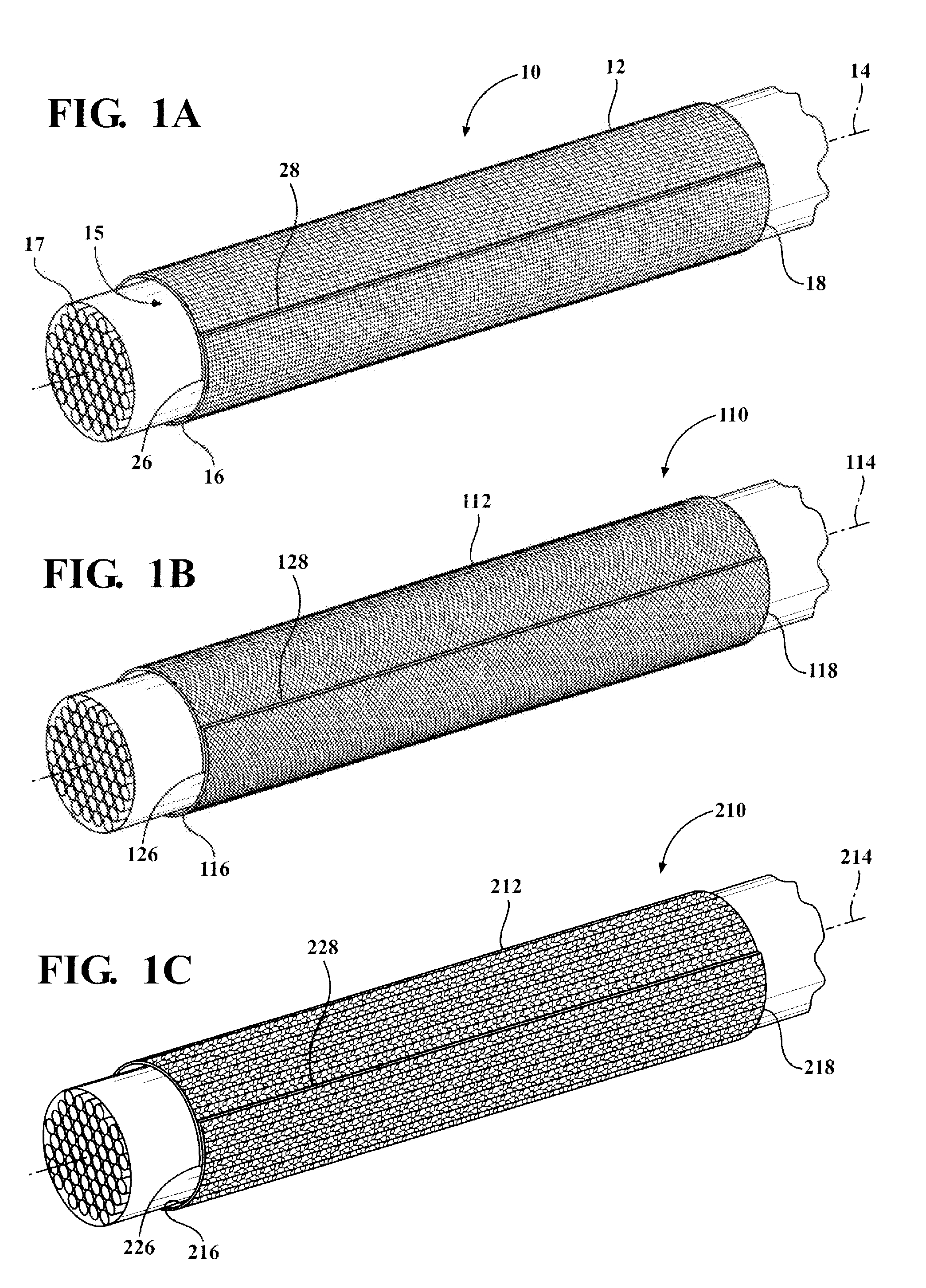
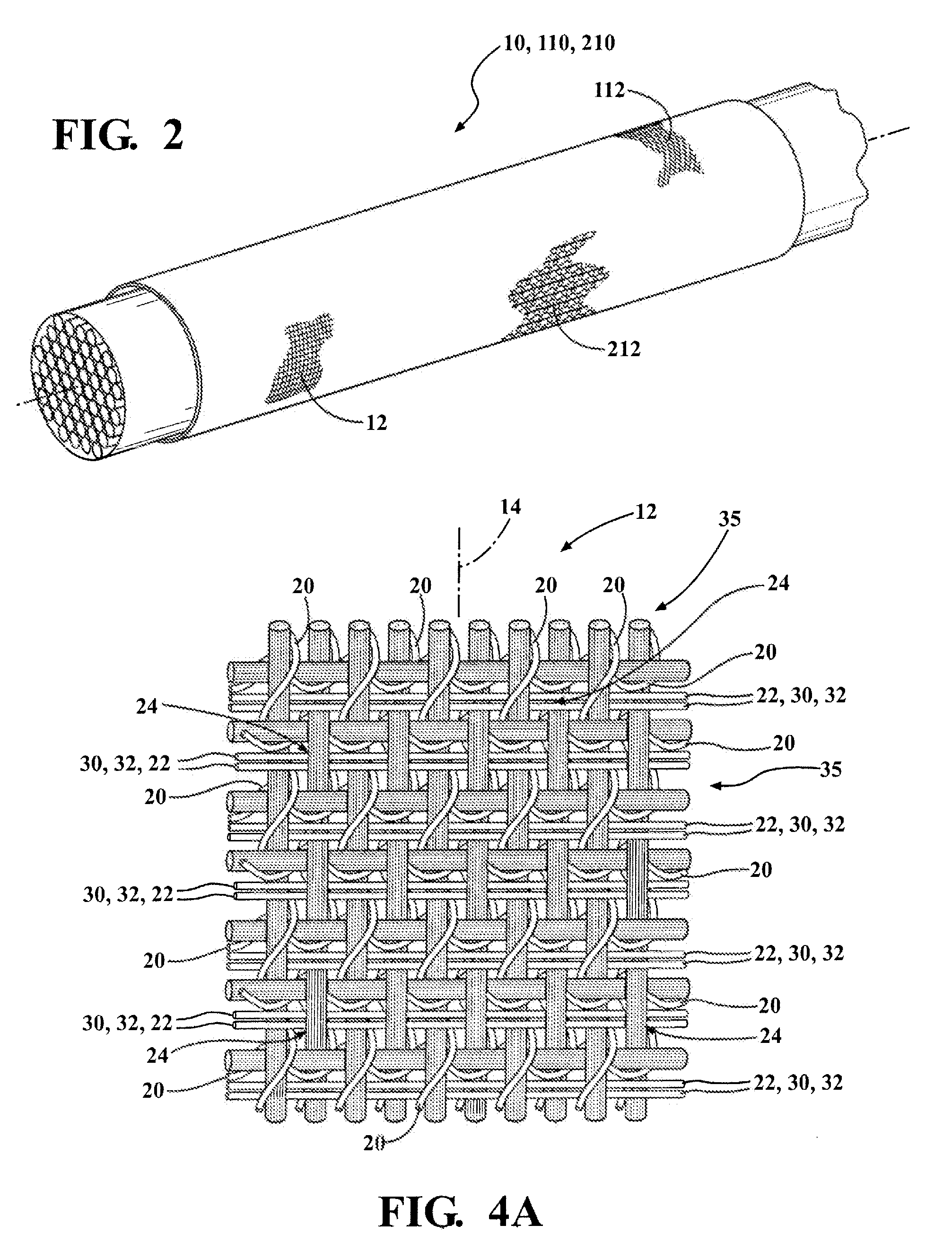
[0038]Referring in more detail to the drawings, FIG. 1A shows a self-wrapping sleeve 10 constructed according in accordance with one presently preferred embodiment of the invention. The sleeve 10 has a wall 12 extending along a longitudinal axis 14 between opposite open ends 16, 18, and forms a cavity 15 for protective receipt of an elongate member or members 17 to be protected, such as wire or a wire harness, by way of example and without limitation. The wall 12 is formed from a plurality of filaments interlaced with one another, wherein the term filaments is intended to include monofilaments and / or multifilaments, with specific reference being given to the type of filament, as necessary, hereafter. At least one of the filaments is provided as a continuous strand of conductive wire 20 (FIGS. 3A-3C) and at least some of the filaments are provided as heat-fusible nonconductive filaments 22 (FIGS. 3D-3F), whether being heat-fusible monofilaments or heat-fusible multifilaments. The hea...


PUM

PropertyMeasurementUnit
temperatureaaaaaaaaaa
diameteraaaaaaaaaa
conductiveaaaaaaaaaa

Abstract

A fabric sleeve for protecting elongate members against at least one of EMI, RFI or ESD and method of construction thereof is provided. The sleeve includes a wall extending along a longitudinal axis between opposite ends. The wall is formed from a plurality of filaments interlaced with one another, with at least one of the filaments being provided as a continuous strand of conductive wire and at least some of the filaments being provided as heat-fusible nonconductive filaments. The heat-fusible nonconductive filaments abut the continuous strand of conductive wire at a plurality of bond joints. The continuous strand of conductive wire is at least partially embedded in bonded, fixed attachment with the heat-fusible nonconductive filaments at the bond joints.

Description

BACKGROUND OF THE INVENTION[0001]1. Technical Field[0002]This invention relates generally to tubular sleeves for protecting elongate members, and more particularly to tubular sleeves having wire filaments that provide protection against at least one of electromagnetic interference, radio frequency interference, and electrostatic discharge.[0003]2. Related Art[0004]It is known that electromagnetic interference (EMI), radio frequency interference (RFI), and electrostatic discharge (ESD) pose a potential problem to the proper functioning of electronic components caused by interference due to inductive coupling between nearby electrical conductors and propagating electromagnetic waves. For example, electrical currents in conductors associated with an electrical power system in an automobile may induce spurious signals in various electronic components, such as an electronic module which controls the functioning of the engine. Such interference could downgrade the performance of control m...

Claims


Application Information

Patent Timeline
Patent Type & Authority Applications(United States)
IPC IPC(8): H05K9/00D03D1/00D03D15/567D04B1/22D04C1/06
CPCH05K9/0079H05K9/009H05K9/0098D04C1/06D04B1/225D03D1/0088D10B2101/20D10B2401/041D10B2505/12D03D15/47D03D15/587D03D1/0043D04C1/02B60R16/0215D03D15/593H05K9/0067H05K9/0081
Inventor HARRIS, DAVID A.CHEN, MING-MINGPIOTROWSKI, MICHAEL
Owner FEDERAL MOGUL POWERTAIN LLC
Why Eureka
Try Eureka