Device for taking a liquid sample by capillarity and associated analysis method

a liquid sampler and capillary technology, applied in the field of liquid samplers, can solve the problems of affecting the quality of liquid samplers, so as to reduce the risk of air bubbles and increase the depth of the channel

Active Publication Date: 2016-01-28
COMMISSARIAT A LENERGIE ATOMIQUE ET AUX ENERGIES ALTERNATIVES
View PDF7 Cites 21 Cited by
  • Summary
  • Abstract
  • Description
  • Claims
  • Application Information

AI Technical Summary

Benefits of technology

[0091]In particular, according to one embodiment of the invention, the channel may comprise a concave part, extending over a first portion lying between a first distance and a second distance with respect to the first end of the channel. Advantageously, this concave part may allow an increase in the depth of the channel.
[0092]Preferably, the first portion is situated close to the first end. Such a configuration may allow a draining of the liquid towards the channel bottom. It also allows a fluid flow limiting the risk of appearance of air bubbles in the channel.

Problems solved by technology

However, the implementation of these solutions is known from the prior art disclosed above, and in particular the one described in European Patent EP 0 821 784 B1, raises several constraints.
For example, the device described in European patent EP 0 821 784 B1 has, in use, a drawback in terms of risk of contamination of the outside of the device by the sampled liquid.
In addition, the liquid is not sufficiently maintained inside the zone formed by the fluid microchannel and the analysis bowl and it may happen that the liquid also flows outside the device by means of the cavity.
Furthermore, where a deposit of reagent in the microchannel is required, the configuration of this device is not really suitable for obtaining a homogeneous deposit of the reagent in the microchannel.
Because of the narrowness and the depth of the fluid microchannel, it is in fact difficult to deposit or dry a reagent homogeneously.
Moreover, the form of the generatrix of the microchannel of this device, that is to say the form of the direction in which the microchannel extends, may accentuate the formation of undesirable air bubbles in the device when the liquid is sampled.
Finally, the configuration of the first end of the microchannel used for collecting the liquid to be analysed is not satisfactory for allowing optimum efficiency of the sampling and facilitating the collection operation.

Method used


Image

  • Device for taking a liquid sample by capillarity and associated analysis method
  • Device for taking a liquid sample by capillarity and associated analysis method
  • Device for taking a liquid sample by capillarity and associated analysis method

Examples


Embodiment Construction

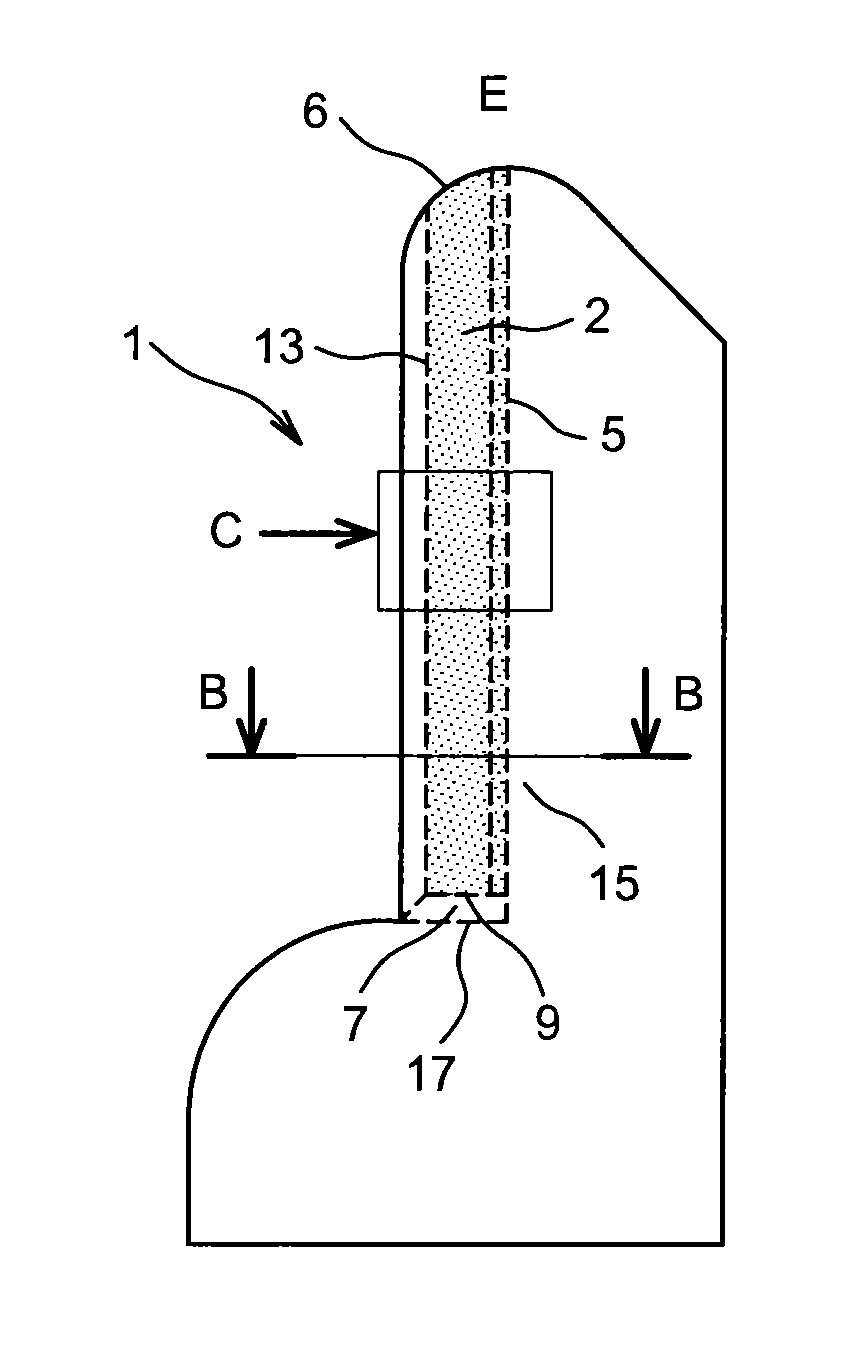
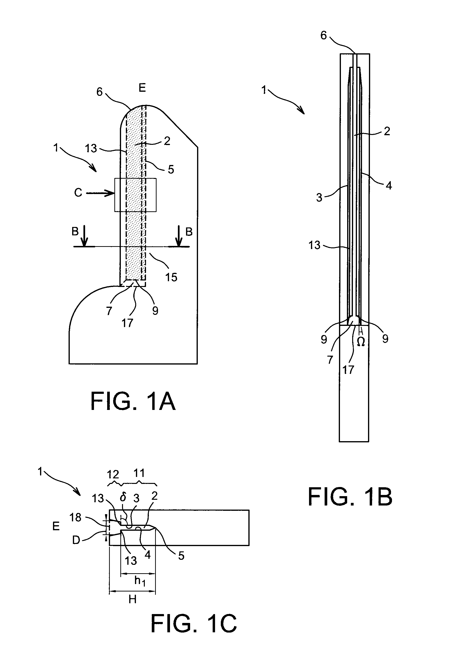
[0126]FIGS. 1A, 1B and 1C show a first example of a device 1 for taking a liquid sample L by capillarity according to the invention.

[0127]FIG. 1A is a profile view of the device 1, FIG. 1B is a view in cross-section along B-B in FIG. 1A and FIG. 1C is a front view along C of the device 1 of FIG. 1A.

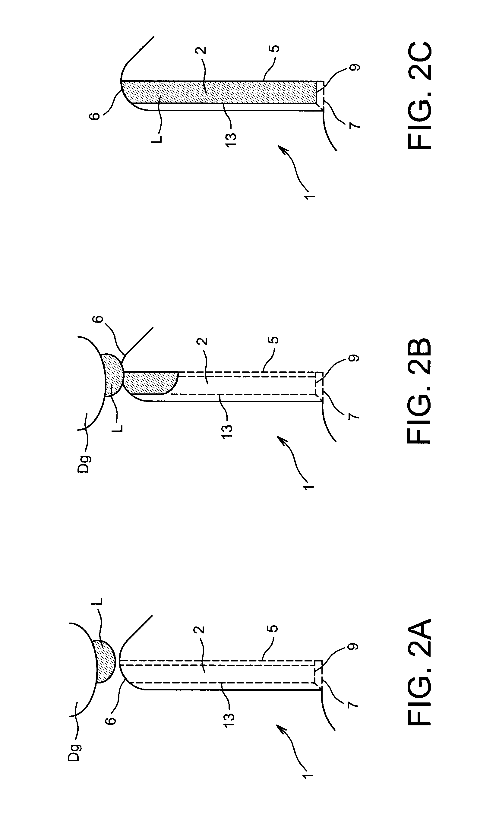
[0128]In accordance with the invention, the device 1 comprises a channel 2 for flow of the liquid L delimited by two internal walls 3 and 4, or lateral walls, between which a channel bottom 5 extends. The distance D, visible in FIG. 1C, between the two internal walls 3 and 4 decreases in the direction of the channel bottom 5. In addition, the channel bottom 2 extends from a first collecting end 6, open to the outside E of the device 1 and able to receive the liquid L, and a second end 7, so as to enable the liquid L to flow by capillarity along the channel bottom 5 from the first end 6 to the second end 7.

[0129]Thus the overall form of the channel 2, defined by the internal walls 3 and 4,...


PUM


Abstract

A device for taking a sample of liquid by capillarity, including a channel for flow of the liquid delimited by two internal walls of the device between which a channel bottom extends, the distance separating the two internal walls decreasing in the direction of the channel bottom, the channel extending between a first collecting end, open onto outside of the device and configured to receive the liquid, and a second end, to enable the liquid to flow by capillarity along the channel bottom from the first end towards the second end. The channel includes, at the second end, a blocking structure to block the flow of liquid in the channel from the first end towards the second end.

Description

TECHNICAL FIELD[0001]The present invention relates to the field of devices for collecting liquid samples, in particular chemical and / or biological samples, intended to be analysed. It relates in particular to the field of devices for sampling liquid by capillarity.[0002]The invention thus proposes a device for taking a sample of liquid by capillarity and a method for analysing a liquid sample taken by means of such a device.PRIOR ART[0003]Numerous devices capable of sampling liquid intended to be analysed are known in the prior art.[0004]For example, test devices are known in the form of paper strips functionalised with reagents necessary to the performance of tests. The liquid sample is then put in contact with one end of the strip and, under the effect of the porosity of the paper and capillary forces, the liquid gradually fills the strip. Then a reagent present on the strip in dried or lyophilised form mixes with the liquid in the course of the filling and the reaction caused can...

Claims


Application Information

Patent Timeline
Patent Type & Authority Applications(United States)
IPC IPC(8): A61B5/15A61B5/151A61B10/00
CPCA61B5/150755A61B5/151A61B10/0045A61B5/150022A61B5/150068A61B5/150251A61B5/150412A61B5/150419A61B5/150748A61B5/15105A61B5/15142A61B5/157G01N1/10B01L3/5027B01L2200/0684B01L2300/161B01L2400/0406A61B5/150358A61B5/150503
Inventor POUTEAU, PATRICKBERTHIER, JEANPOHER, VINCENT
Owner COMMISSARIAT A LENERGIE ATOMIQUE ET AUX ENERGIES ALTERNATIVES
Why Eureka
Try Eureka