Improved downlights

Inactive Publication Date: 2016-01-28
GIGAPHOTON
View PDF7 Cites 3 Cited by
  • Summary
  • Abstract
  • Description
  • Claims
  • Application Information

AI Technical Summary

Benefits of technology

[0005]According to the present invention a lighting unit for mounting in an aperture comprises a casing and a heat sink mounted to one side of the casing, a light source mounted on a front side of a circuit board, the circuit board including control circuitry for the light source, the heat sink provided in thermal contact with a rear side of the circuit board and a lens arrangement located to the front side of the circuit board, the circuit board and the light source being located in the casing, wherein the circuit board comprises a ceramic circuit board, the arrangement being such that heat generated in use by the light source and control circuitry is transferred by conduction through the circuit board to the rear side of the circuit board and into the heat sink.
[0006]Preferably the ceramic circuit board comprises a ceramic substrate having a nano particle coating. Such cerami

Problems solved by technology

They are particularly neat and unobtrusive in their appearance, since almost the entire downlight fitting is concealed behind a ceiling or other suitable panel or surface, whilst giving out a pleasing light.
Downlights generate significa

Method used


Image

  • Improved downlights
  • Improved downlights
  • Improved downlights

Examples


Example

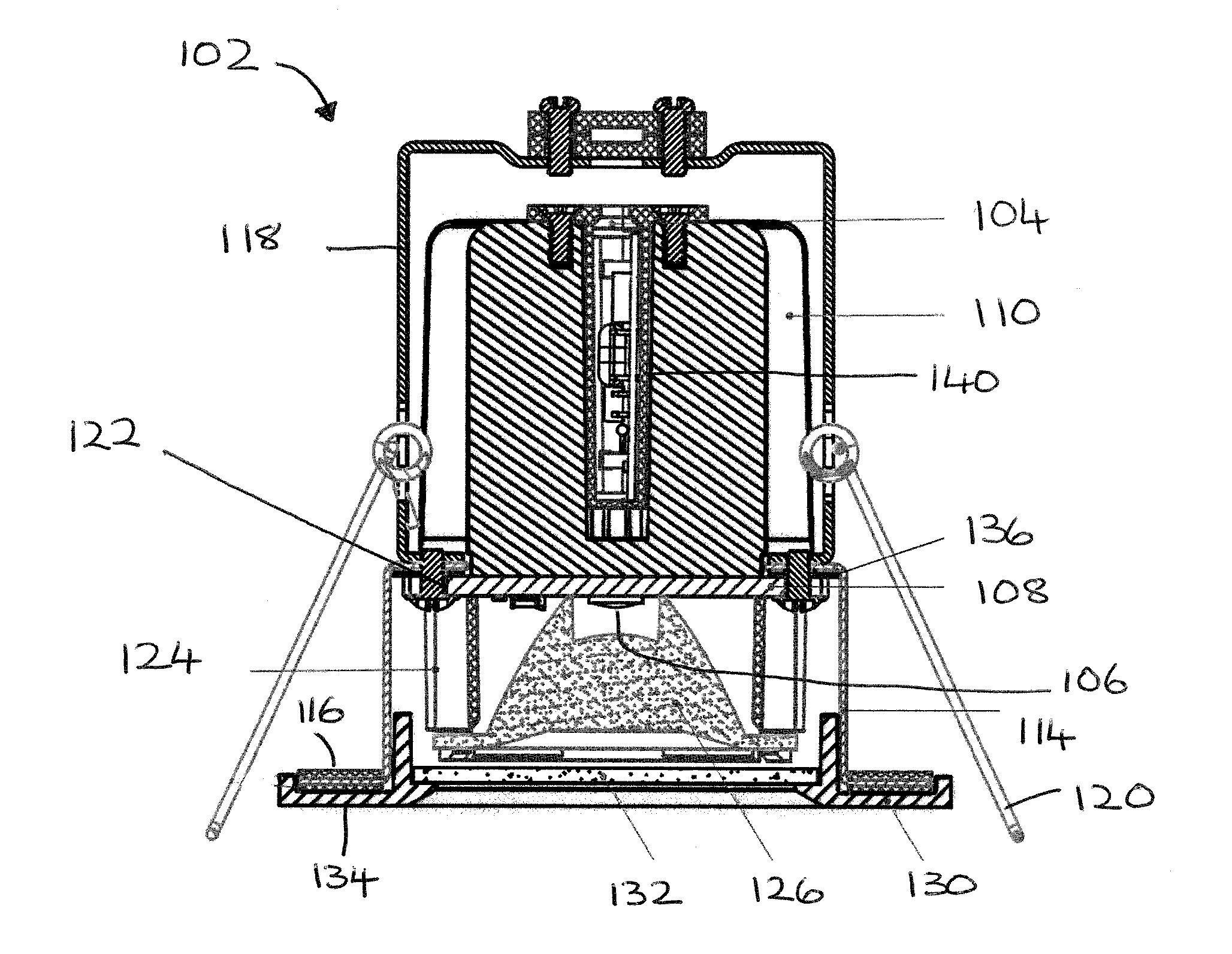
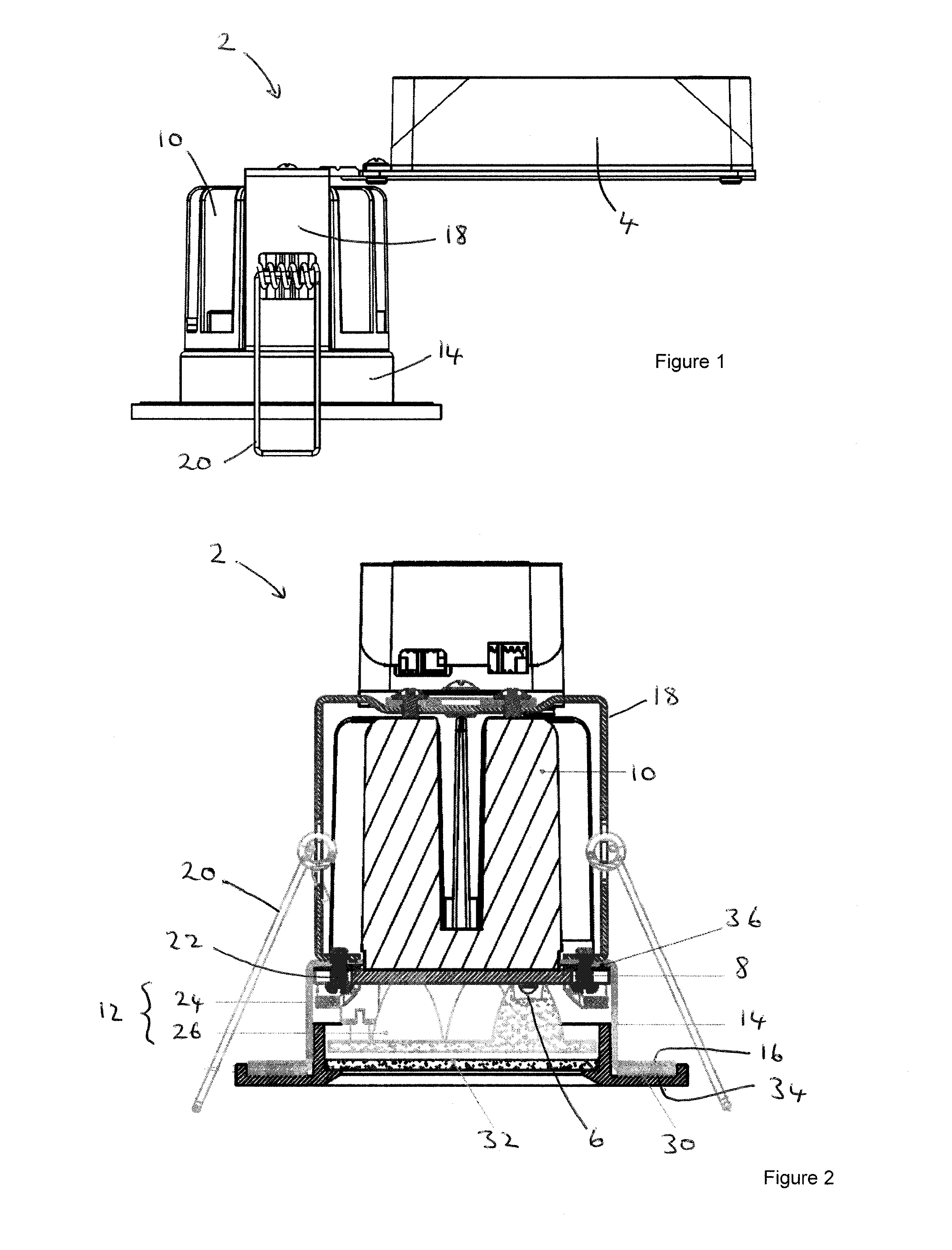
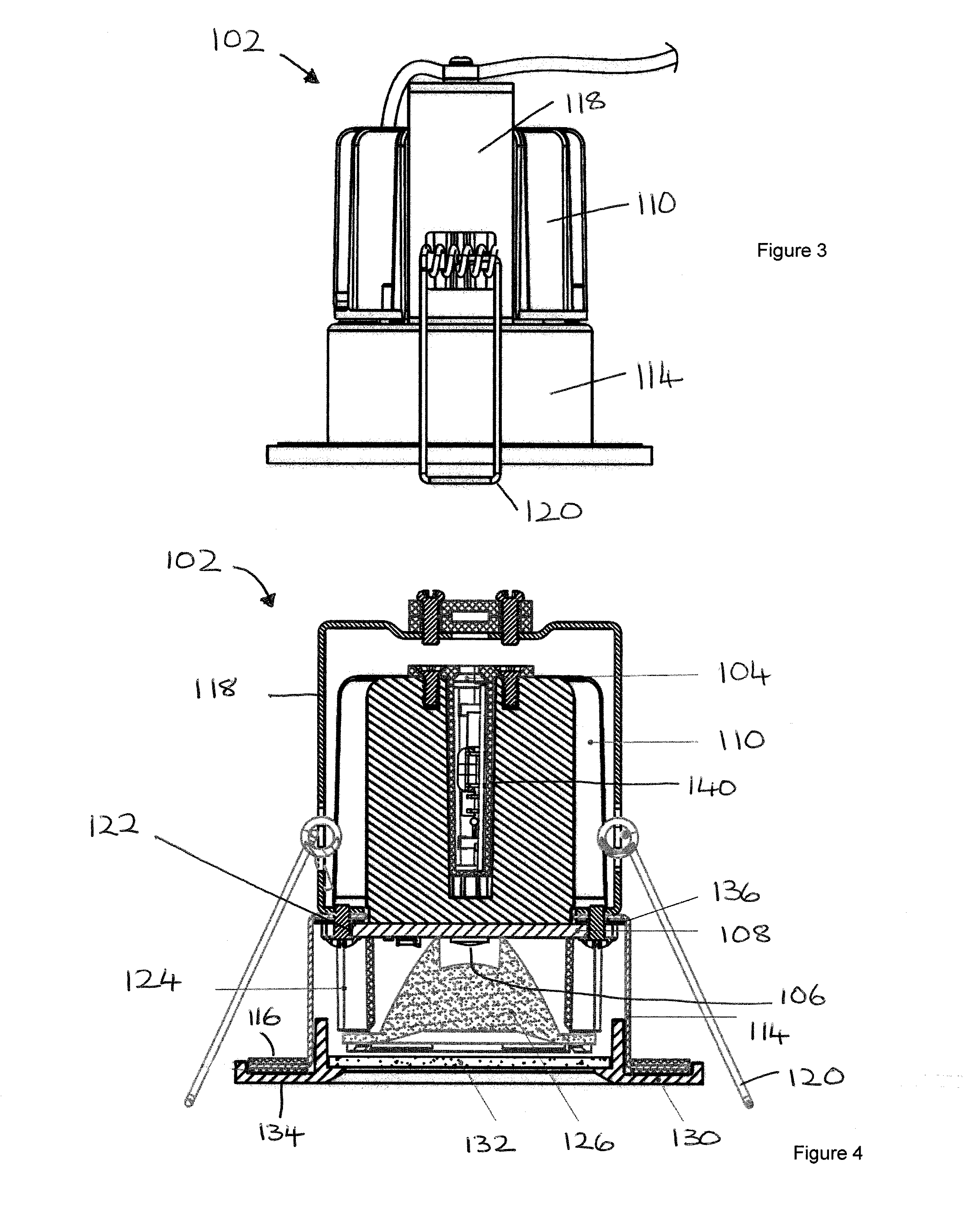
[0017]Referring first to FIGS. 1 and 2 there is shown a lighting unit is the form of a downlight unit 2 incorporating a terminal block, transformer unit or driver 4 provided on a mounting arm secured at one end to an upper end of the downlight unit 2.

[0018]The downlight unit comprises a light source 6 mounted to a circuit board 8, for example a printed circuit board, the circuit board including control circuitry for the light source 6, a heat sink 10 connected to a cylindrical casing, the heat sink 10 being provided to a rear side of the circuit board 8 and a lens arrangement 12 located at a front side of the circuit board.

[0019]The term “cylindrical casing” means conforming approximately to the shape of a hollow cylinder. It will be understood that a misshapen cylinder will work equally well. Similarly, while the embodiments show a generally circular cylindrical tubular body other sections may be used with amendment to the sectional shape of other components.

[0020]The light source ...


PUM


Abstract

Improved lighting units are disclosed comprising a casing (14, 114) and a heat sink (11, 110) mounted to the casing (14, 114), a light source (6, 106) mounted to a front side of a circuit board (8, 108), the circuit board (8, 108) including control circuitry for the light source (6, 106), the heat sink (10, 110) provided in thermal contact with a rear side of the circuit board (8, 108) and a lens arrangement (12) located at the front side of the circuit board (8, 108), the circuit board (8, 108) and the light source (6, 106) being located in the casing (14, 114) wherein the circuit board (8, 108) comprises a ceramic circuit board, the arrangement being such that heat generated in use by the light source (6, 106) and control circuitry is transferred by conduction through the circuit board (8, 108) to the rear side of the circuit board (8, 108) and into the heat sink (10, 110).

Description

FIELD OF THE INVENTION[0001]The present invention relates to an improved lighting unit, in particular, an improved construction of downlight utilising an LED light sourceBACKGROUND OF THE INVENTION[0002]Downlight fittings or downlighters are a form of lighting unit becoming more and more widely used as light sources in domestic and commercial environments. They are particularly neat and unobtrusive in their appearance, since almost the entire downlight fitting is concealed behind a ceiling or other suitable panel or surface, whilst giving out a pleasing light. However, downlights suffer from a number of disadvantages.[0003]Downlights generate significant amounts of heat. It is important to prevent overheating of the lighting element, and associated control circuit, since overheating will have obvious effects on the light output and service life of these components. Indeed, excessive temperatures will cause electronic components to fail leading to premature failure of the lighting un...

Claims


Application Information

Patent Timeline
IPC IPC(8): F21S8/02F21V5/04F21V23/02F21V29/15F21V29/70
CPCF21S8/026F21V29/70F21Y2101/02F21V23/02F21V5/04F21V29/15F21V13/02F21V21/046F21Y2115/10F21V23/005
Inventor JOHNSON, ANDREW
Owner GIGAPHOTON
Why Eureka
Try Eureka