
Latent fingerprint detectors and fingerprint scanners therefrom

Active Publication Date: 2016-01-28
LEIDOS INNOVATIONS TECH INC
View PDF0 Cites 10 Cited by
  • Summary
  • Abstract
  • Description
  • Claims
  • Application Information

AI Technical Summary

Benefits of technology

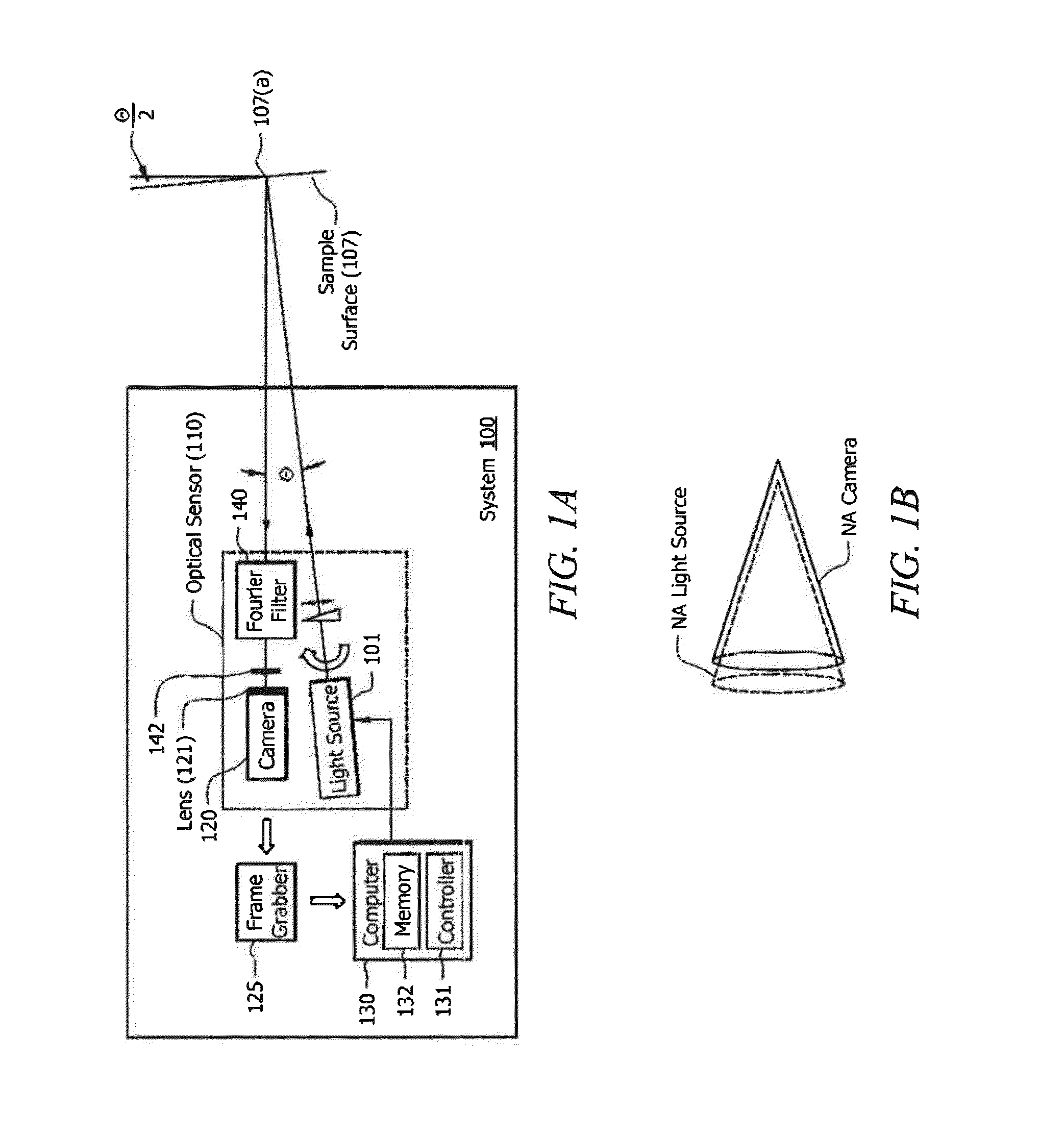
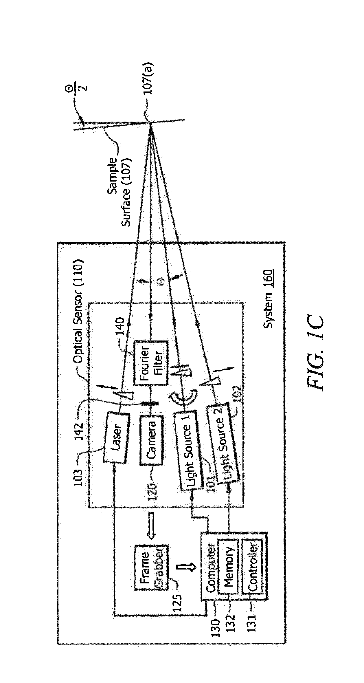
The critically aligned optical sensor and camera settings act as a filter that reduces diffuse reflections from scattering surfaces, resulting in a "geometric filter" that only takes in glare. Additionally, the numerical aperture of the lens or optical system is set to zero, which further enhances the glare rejection. This allows for improved photon processing and eliminates the effect of diffuse reflection, resulting in better image quality.

Problems solved by technology

Such conventional methods can present an immediate dilemma in that they force the investigator to make a decision as to whether to dust for prints versus swabbing for DNA or chemical evidence present in the makeup of the print.
Furthermore, such conventional methods are time- consuming and inconsistent, requiring some amount of trial-and-error on the part of an investigator before finding a technique suitable for a particular fingerprint composition and fingerprint-bearing surface combination.

Method used


Image

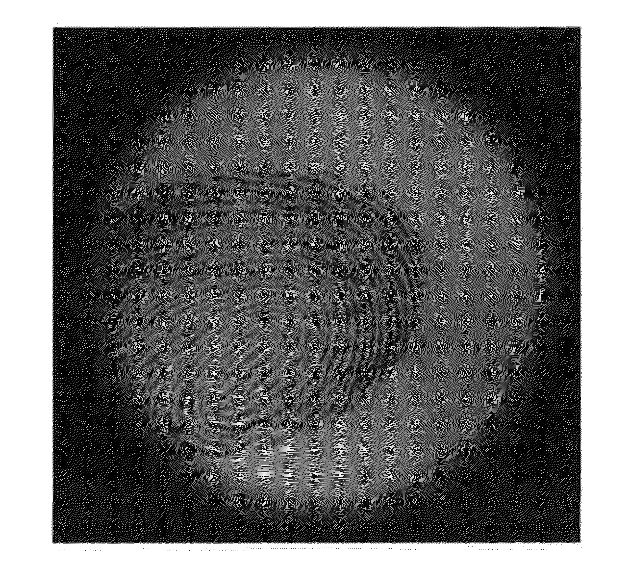
  • Latent fingerprint detectors and fingerprint scanners therefrom
  • Latent fingerprint detectors and fingerprint scanners therefrom
  • Latent fingerprint detectors and fingerprint scanners therefrom

Examples


Embodiment Construction

[0044]Disclosed embodiments are described with reference to the attached figures, wherein like reference numerals, are used throughout the figures to designate similar or equivalent elements. The figures are not drawn to scale and they are provided merely to illustrate aspects disclosed herein. Several disclosed aspects are described below with reference to example applications for illustration. It should be understood that numerous specific details, relationships, and methods are set forth to provide a full understanding of the embodiments disclosed herein. One having ordinary skill in the relevant art, however, will readily recognize that the disclosed embodiments can be practiced without one or more of the specific details or with other methods. In other instances, well-known structures or operations are not shown in detail to avoid obscuring aspects disclosed herein. Disclosed embodiments are not limited by the illustrated ordering of acts or events, as some acts may occur in di...


PUM


Abstract

This document relates to systems and method for latent fingerprint detection using specular reflection (glare). An exemplary system may include a light source alignment portion configured to align a light source at an illumination angle relative to a sample surface such that the light source illuminates a sample surface so that the surface produces specular reflection. The system may also include a specular reflection discriminator that directs the produced specular reflection to an optical detector aligned relative to said sample surface at an alignment angle that is substantially equal to an angle of reflection of the produced specular reflection. Preferably, the directed specular reflection does not saturate the optical detector; and the optical detector captures the specular reflection from the sample surface and generates image data using essentially only the specular reflection.

Description

CROSS REFERENCE TO RELATED APPLICATIONS[0001]This application is a Continuation of U.S. application Ser. No. 14 / 260,549 filed Apr. 24, 2014, which is a Continuation of U.S. application Ser. No. 13 / 976,177 filed Jul. 29, 2013, now U.S. Pat. No. 8,805,033 issued Aug. 12, 2014, which is a U.S. national phase of International Application No. PCT / US2011 / 059008 filed Nov. 2, 2011, which is a Continuation of U.S. application Ser. No. 13 / 049,351 filed Mar. 16, 2011, now U.S. Pat. No. 8,437,517 issued May 7, 2013, which claims the benefit of U.S. Provisional Application No. 61 / 409,753 filed Nov. 3, 2010, and incorporated herein by reference in their entirety.FIELD[0002]Disclosed embodiments relate to non-contact automatic optical detection of latent fingerprints.BACKGROUND[0003]Latent prints are invisible fingerprint impressions left on solid surfaces following surface contact caused by the perspiration on the ridges of an individual's skin on their fingers coming in contact with a surface a...

Claims


Application Information

Patent Timeline
IPC IPC(8): G06K9/00G01N21/94
CPCG01N21/94G06K9/00033G06V40/1312G01N21/8851G01N2201/06113G01N2201/10
Inventor MIESAK, EDWARDGOLD, JR., V. EDWARD
Owner LEIDOS INNOVATIONS TECH INC
Learn More