

Resonator element, manufacturing method for resonator element, resonator, electronic device, and moving object
a manufacturing method and technology for resonators, applied in the direction of generators/motors, piezoelectric/electrostrictive transducers, transducer types, etc., can solve the problems of difficult to obtain satisfactory q values and insufficient electric field efficiency, and achieve high reliability
- Summary
- Abstract
- Description
- Claims
- Application Information
AI Technical Summary
Benefits of technology
Problems solved by technology
Method used
Image

Examples
first embodiment
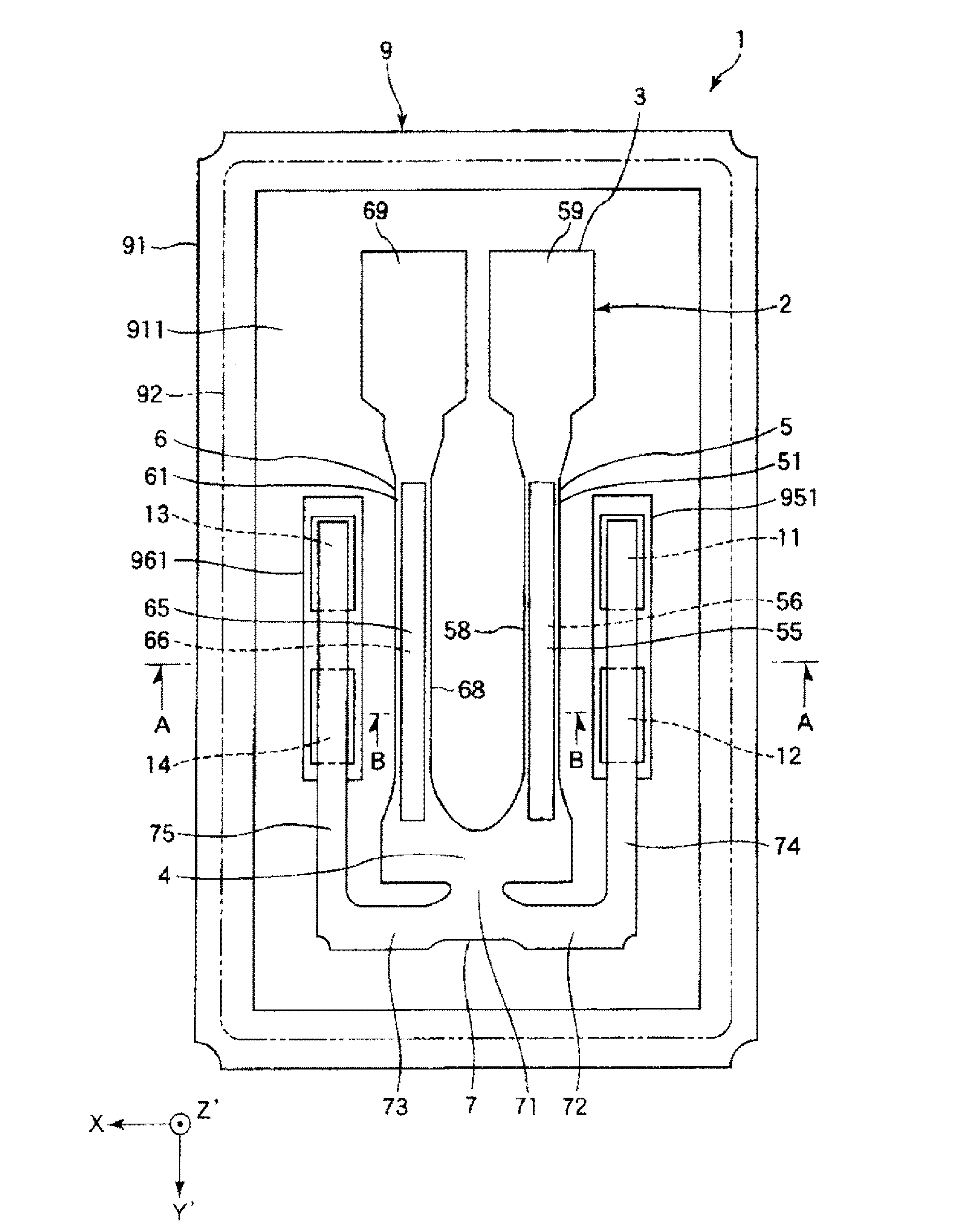
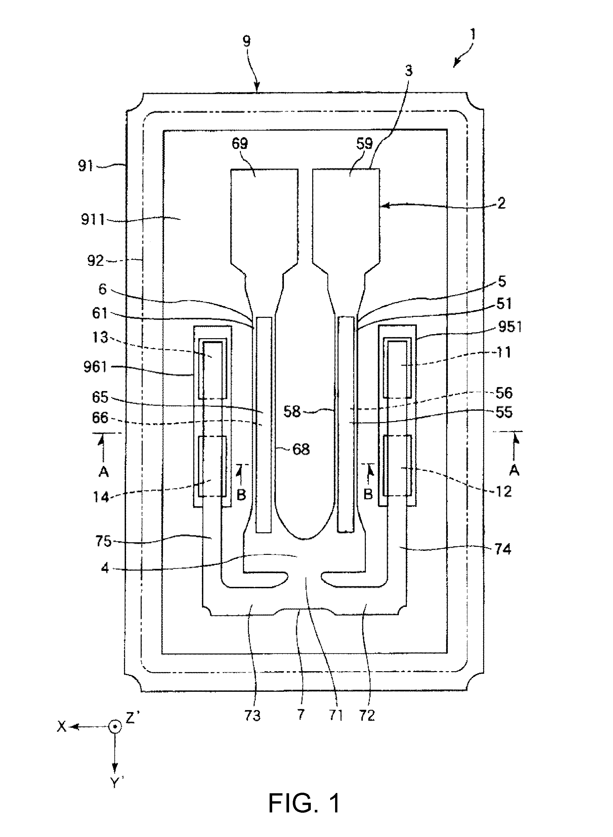
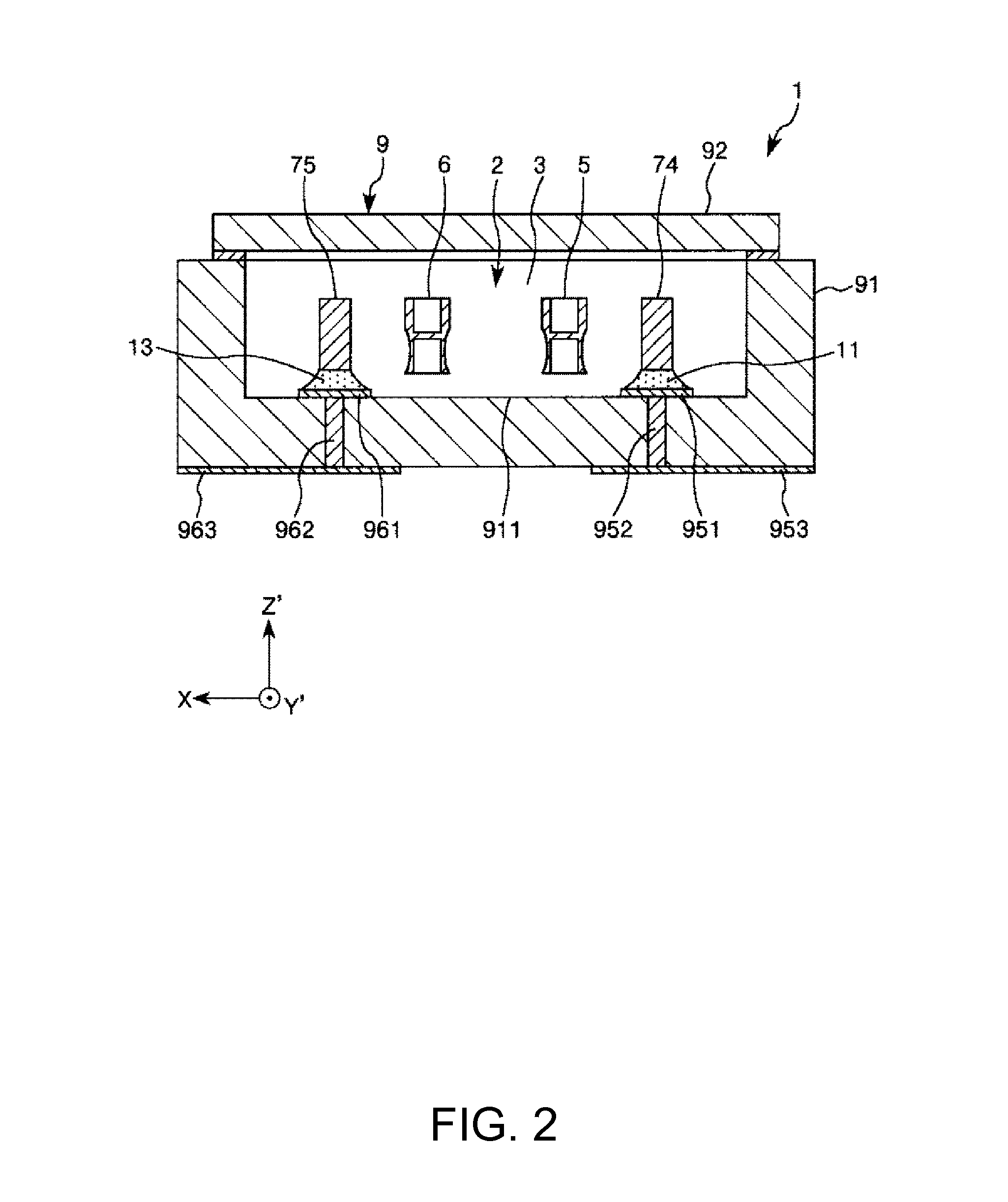
[0058]FIG. 1 is a plan view showing a first embodiment of the resonator according to the invention. FIG. 2 is an A-A line sectional view of FIG. 1. FIG. 3 is a sectional view (a B-B line sectional view of FIG. 1) of a resonator element of the resonator shown in FIG. 1. FIGS. 4A to 6B are respectively sectional views for explaining a manufacturing method for the resonator element of the resonator shown in FIG. 1.
[0059]An resonator 1 shown in FIGS. 1 and 2 includes a resonator element 2 and a package 9 that houses the resonator element 2. The resonator element 2 and the package 9 are explained in detail below in order.
Resonator Element
[0060]As shown in FIGS. 1 to 3, the resonator element 2 in this embodiment includes a resonator substrate (a work piece) 3 and first and second electrodes for driving 84 and 85 formed on the resonator substrate 3. Note that, in FIGS. 1 and 2, for convenience of explanation, the first and second electrodes for driving 84 and 85 are not shown.
[0061]In this...
second embodiment
[0139]FIG. 7 is a plan view showing a second embodiment of the resonator according to the invention. FIG. 8 is a cross sectional view of the resonator shown in FIG. 7. FIGS. 9A and 9B are diagrams showing a resonating arm for driving of the resonator shown in FIG. 7. FIG. 9A is an enlarged plan view and FIG. 9B is an enlarged cross sectional view. FIGS. 10A and 10B are diagrams showing a resonating arm for detection of the resonator shown in FIG. 7. FIG. 10A is an enlarged plan view and FIG. 10B is an enlarged cross sectional view. FIG. 11 is a perspective view of a main part of a resonator element of the resonator shown in FIG. 7. FIGS. 12A and 12B are diagrams for explaining detection modes of the resonator element of the resonator shown in FIG. 7.
[0140]Note that, in the following explanation, as three axes orthogonal to (crossing) one another, an x axis (a first axis), a y axis (a first axis), and a z axis (a first axis) are assumed. In FIGS. 7 to 11, the axes are shown. A direct...
third embodiment
[0184]FIG. 13 is a plan view showing a resonator element in a third embodiment according to the resonator of the invention. FIG. 14 is a plan view showing electrodes of the resonator element shown in FIG. 13. FIG. 15 is a plan view (a see-through view) showing the electrodes of the resonator element shown in FIG. 13. FIGS. 16A and 16B are diagrams for explaining the operation of the resonator element shown in FIG. 13.
[0185]Note that, in the following explanation, for convenience of explanation, the paper surface front side of FIGS. 13 and 14 is also referred to as “upper side” and the paper surface depth side is also referred to as “lower side”. In FIGS. 13, 14, and 6, for convenience of explanation, illustration of electrodes is omitted.
[0186]The third embodiment is explained below centering on differences from the first and second embodiments. Explanation of similarities is omitted.
Basic Structure of a Resonator Element
[0187]A resonator includes a resonator element 1B shown in FIG...
PUM
 Abstract
Description
Claims
Application Information