Eureka AIR delivers breakthrough ideas for toughest innovation challenges, trusted by R&D personnel around the world.

Micromechanical sensor and method for manufacturing a micromechanical sensor

Active Publication Date: 2016-02-04
ROBERT BOSCH GMBH
View PDF17 Cites 4 Cited by
  • Summary
  • Abstract
  • Description
  • Claims
  • Application Information

AI Technical Summary

Benefits of technology

The present invention allows for the creation of flexible compensation elements in the same step as the creation of other components in a micromechanical sensor. This self-adjusting method improves the performance of the sensor by adapting the shape and arrangement of the compensation elements to the angle of the trench during the manufacturing process.

Problems solved by technology

The disadvantage with the known micromechanical sensors is that the flanks of the silicon structures (also referred to as etching flanks or trench flanks) created during the structuring of the functional layer are frequently inclined by an angle (also referred to as etching angle or trench angle) with respect to a normal direction which is essentially perpendicular to the main extension plane of the substrate, so that in this way a deviating movement (faulty deflection) of the two movable masses is induced.
The faulty deflection also occurs when the micromechanical sensor is in a rest position, so that a wobbling motion of the two seismic masses is caused, an error signal (i.e., a so-called quadrature signal) being generated.

Method used


Image

  • Micromechanical sensor and method for manufacturing a micromechanical sensor
  • Micromechanical sensor and method for manufacturing a micromechanical sensor
  • Micromechanical sensor and method for manufacturing a micromechanical sensor

Examples


Embodiment Construction

[0032]Identical parts are always denoted by the same reference numerals in the various figures and are therefore generally also cited or mentioned only once.

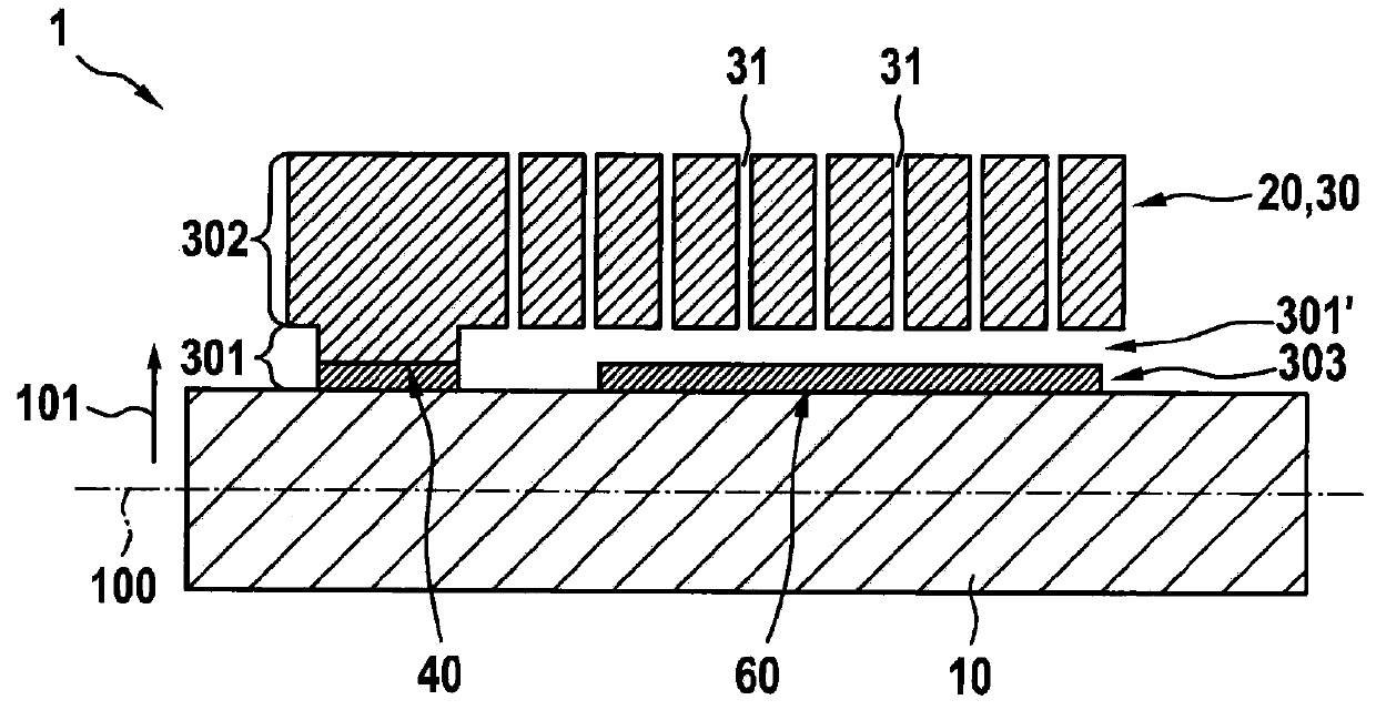
[0033]FIG. 1 shows a schematic cross-sectional view of a micromechanical sensor 1 according to one specific embodiment of the present invention.

[0034]Micromechanical sensor 1 is designed as a rotation rate sensor and / or acceleration sensor, for example.

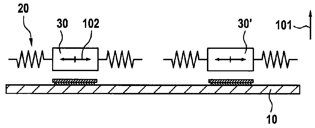
[0035]Micromechanical sensor 1 includes a substrate 10 having a main extension plane 100, a normal direction 101 which is essentially perpendicularly oriented to the main extension plane 100 being shown here. The micromechanical sensor moreover includes a mass element 30 movable relative to substrate 10, movable mass element 30 being coupled via a spring structure 20 (only indicated here) to substrate 10 or being joined to substrate 10 in a spring-elastic manner. Mass element 30 and spring structure 20 are also referred to in summary here as movable silicon structures 20, 30.

[0036...


PUM


Abstract

A micromechanical sensor is provided as including a substrate having a main extension plane and a mass element movable relative to the substrate, the movable mass element being coupled to the substrate via a spring structure, the spring structure including a first and a second spring element, the first and second spring elements extending essentially in parallel to each other in sections and being coupled to each other in sections, the spring structure including a first and a second compensation element for quadrature compensation, the first compensation element being connected to the first spring element, the second compensation element being connected to the second spring element, the first spring element having a first spring structure width extending along a transverse direction, the second spring element having a second spring structure width extending along the transverse direction, the first compensation element in a first subarea extending in parallel to the transverse direction along a first width, the first spring structure width and the first width being different, the second compensation element in a second subarea extending in parallel to the transverse direction along a second width, the second spring structure width and the second width being different.

Description

FIELD OF THE INVENTION[0001]The present invention is directed to a micromechanical sensor.BACKGROUND INFORMATION[0002]Such micromechanical sensors are generally known. For example, micromechanical sensors are used to detect accelerations and / or rotation rates, the micromechanical sensor including a substrate and silicon structures movable relative to the substrate.[0003]For example, the movable silicon structures include two movable masses which are moved along a drive plane antiparallel to each other, a deflection movement of the two masses out of the drive plane being capacitively detected in order to determine a rotation rate of the micromechanical sensor. The drive plane may be oriented essentially in parallel or perpendicularly to the main extension plane of the substrate.[0004]Such movable silicon structures are typically manufactured in two consecutive steps, the silicon structures initially being created in an etching process by structuring a functional layer. Subsequently t...

Claims


Application Information

Patent Timeline
IPC IPC(8): G01C19/5712
CPCG01C19/5712B81B3/0054B81B7/02B81C1/00658G01C19/5769G01P15/125G01C19/5621G01C19/5656G01C19/5733
Inventor REINMUTH, JOCHENMAUL, ROBERT
Owner ROBERT BOSCH GMBH
Why Eureka
Eureka Blog
Learn More