Unposition sensor for permanent magnet linear motor

A permanent magnet linear motor and sensor technology, which is used in the control of generators, motor generators, and electromechanical brakes, and can solve problems such as difficulty in detection.

Inactive Publication Date: 2014-01-08
SOUTHEAST UNIV
View PDF2 Cites 46 Cited by
  • Summary
  • Abstract
  • Description
  • Claims
  • Application Information

AI Technical Summary

Problems solved by technology

[0004] Purpose of the invention: In order to overcome the disadvantages brought by mechanical sensors and solve the problem of difficult position detection at zero speed and low speed, the purpose of this invention is to provide a positionless sensor for permanent magnet linear motors, which can target different speeds To

Method used


Image

  • Unposition sensor for permanent magnet linear motor
  • Unposition sensor for permanent magnet linear motor
  • Unposition sensor for permanent magnet linear motor

Examples


Embodiment Construction

[0049] The present invention will be further described below in conjunction with the accompanying drawings.

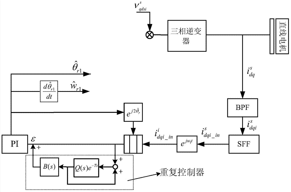
[0050] A positionless sensor for a permanent magnet linear motor, including an initial position detection module, a low-speed section position detection module, a medium-high speed section position detection module, and a transition area position detection module. The mover position of the permanent magnet linear motor is determined by combining each module below The process of obtaining the estimated value of the angle will be described.

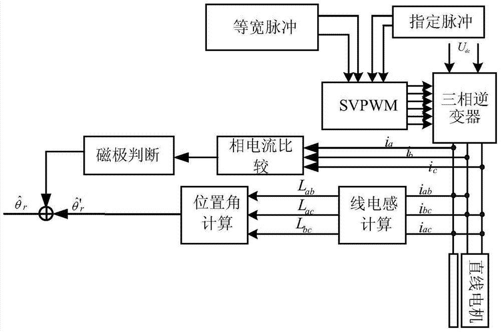
[0051] Initial position detection module

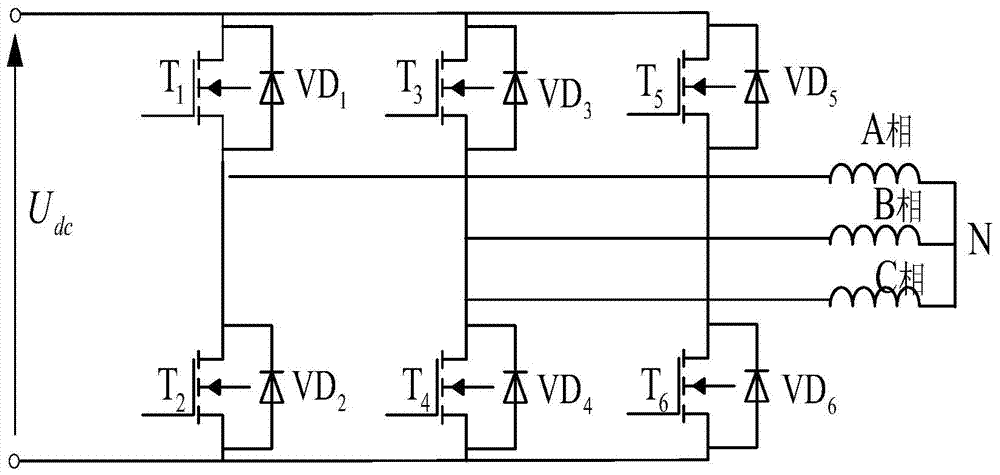
[0052] Such as figure 1 As shown, before the motor starts, the initial position needs to be detected. The method used in this case is: firstly, the inductance value of the three-phase line is calculated by applying a specified pulse to the three-phase inverter, and then combined with the average value of the self-inductance of each phase winding of the motor The initial position of the mo...


PUM


Abstract

The invention discloses an unposition sensor for a permanent magnet linear motor. Before a motor starts, a designated trigger signal is inputted into an inverter, a corresponding line inductance value is solved, the calculation is realized by combining the existing inductive parameters of the motor for preliminarily obtaining an initial position of a linear servo motor and then high-frequency voltage is immediately introduced to judge the direction of a magnetic pole of the rotor; after the motor starts, the position of the rotor is detected at the low-speed phase in real time by a method of combining the injection of the high-frequency voltage with the repetition of a controller; position information of the rotor is acquired at the middle-high speed phases in real time by a method of combining a sliding-mode observer based on an extended counter electromotive force model with a saturation function algorithm. According to the unposition sensor disclosed by the invention, an initial position detection method, a rotating high-frequency injection method, repeated control and the sliding-mode observer are combined together, so that the position information of the linear servo motor can be accurately and effectively detected, the defects caused by the existence of a mechanical sensor are overcome and the reliability of the system is improved.

Description

technical field [0001] The invention relates to a positionless sensor for a permanent magnet linear motor, more specifically a positionless sensor combining initial position detection, a sliding mode observer, rotating high-frequency voltage injection and a repeating controller. Background technique [0002] At present, due to the increasing demand for speed, acceleration, precision and working stroke in the field of CNC machining, new CNC machine tools gradually tend to use linear permanent magnet motors as feed drive motors to replace the traditional "rotary servo motor + ball wire The high-performance CNC machine tool drive system widely adopts vector control and direct torque control strategies, and they all need position sensors to provide feedback signals of speed and mover position. However, in general, CNC machine tools use mechanical position sensors to detect the speed of the motor and the position of the mover, such as photoelectric encoders and resolvers. Howeve...

Claims


Application Information

Patent Timeline
IPC IPC(8): H02P21/14
Inventor 余海涛孟高军胡敏强黄磊须晨凯张笑薇陈中显吴涛
Owner SOUTHEAST UNIV
Why Eureka
Try Eureka