
A device suitable for removing matter from inside the lumen and the wall of a body lumen

a technology of thrombosis and lumens, which is applied in the field of thrombosis devices, can solve the problems of difficult to remove long thrombosis, no filter is suitable, and the sac needs to be extremely long, so as to facilitate the delivery of the devi

Active Publication Date: 2016-02-11
THE NAT UNIV OF IRELAND GALWAY
View PDF13 Cites 46 Cited by
  • Summary
  • Abstract
  • Description
  • Claims
  • Application Information

AI Technical Summary

Benefits of technology

The invention is a device that can be used to remove obstructions from tapering lumens such as valves. It consists of a cage that can be expanded and contracted along the lumen walls to remove the obstacle. The device has a control mechanism that exerts a force on the cage to keep it expanded, until the resistance force of the lumen exceeds the total resistance force. This action allows the cage to move along the lumen walls and effect a scraping / collecting action. The device can be easily inserted and controlled to remove blockages from tapering lumens.

Problems solved by technology

This is a fast way to extract small emboli but for large clot the sac need to be extremely long.
Neither of the filters are suitable for large tapered veins with thrombosis.
Because filters are not designed to be moved along vessels after deployment,this makes it difficult to remove long thrombus.
The existing devices and methods described above do not have a high performance in harvesting large volumes of thrombus and also thrombus in large and / or tapered and / or branched vessels.
Limitations associated with these devices include procedural duration and thrombus removal efficiency.

Method used


Image

  • A device suitable for removing matter from inside the lumen and the wall of a body lumen
  • A device suitable for removing matter from inside the lumen and the wall of a body lumen
  • A device suitable for removing matter from inside the lumen and the wall of a body lumen

Examples


Embodiment Construction

[0143]Cage and Filter

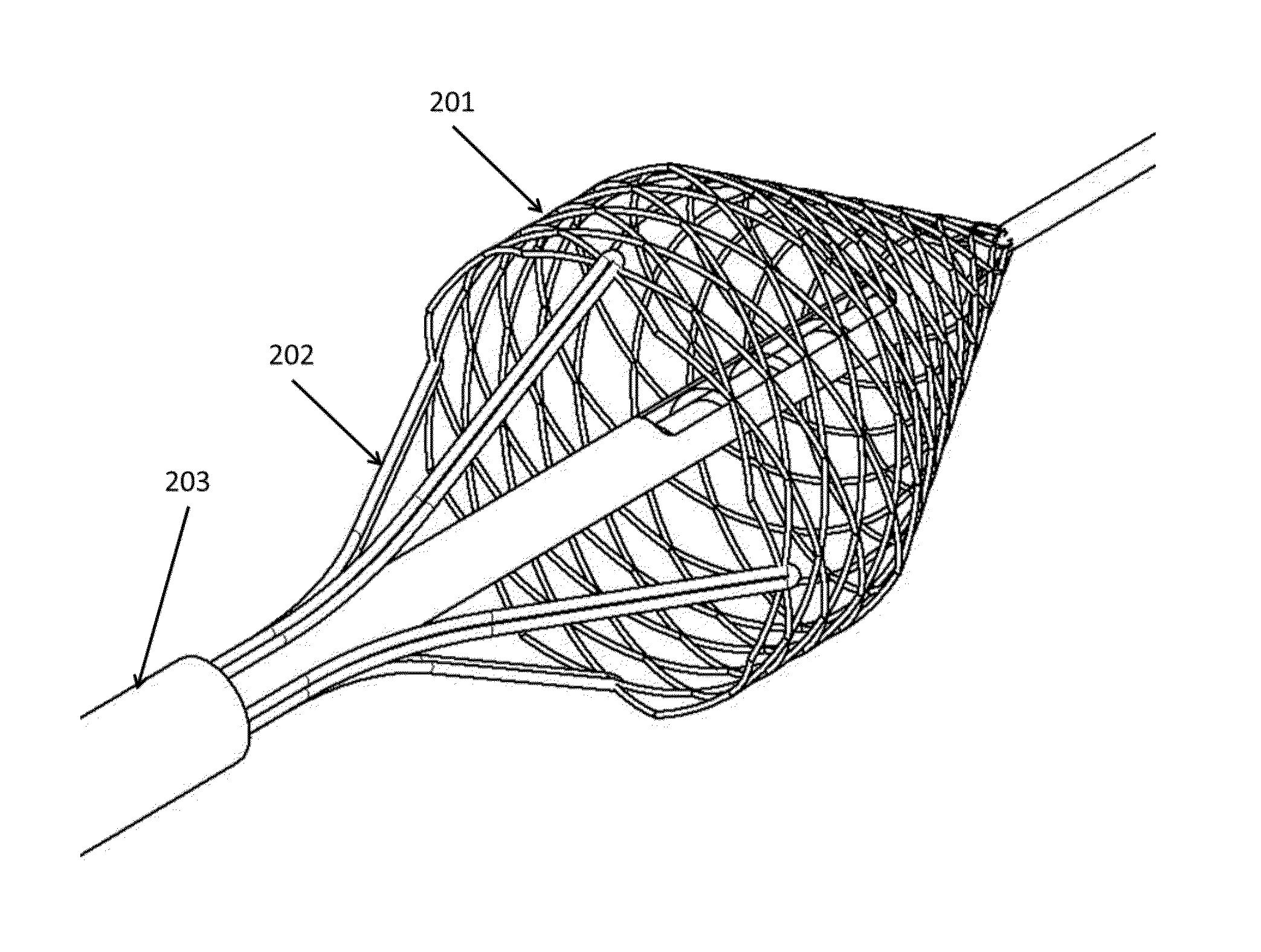
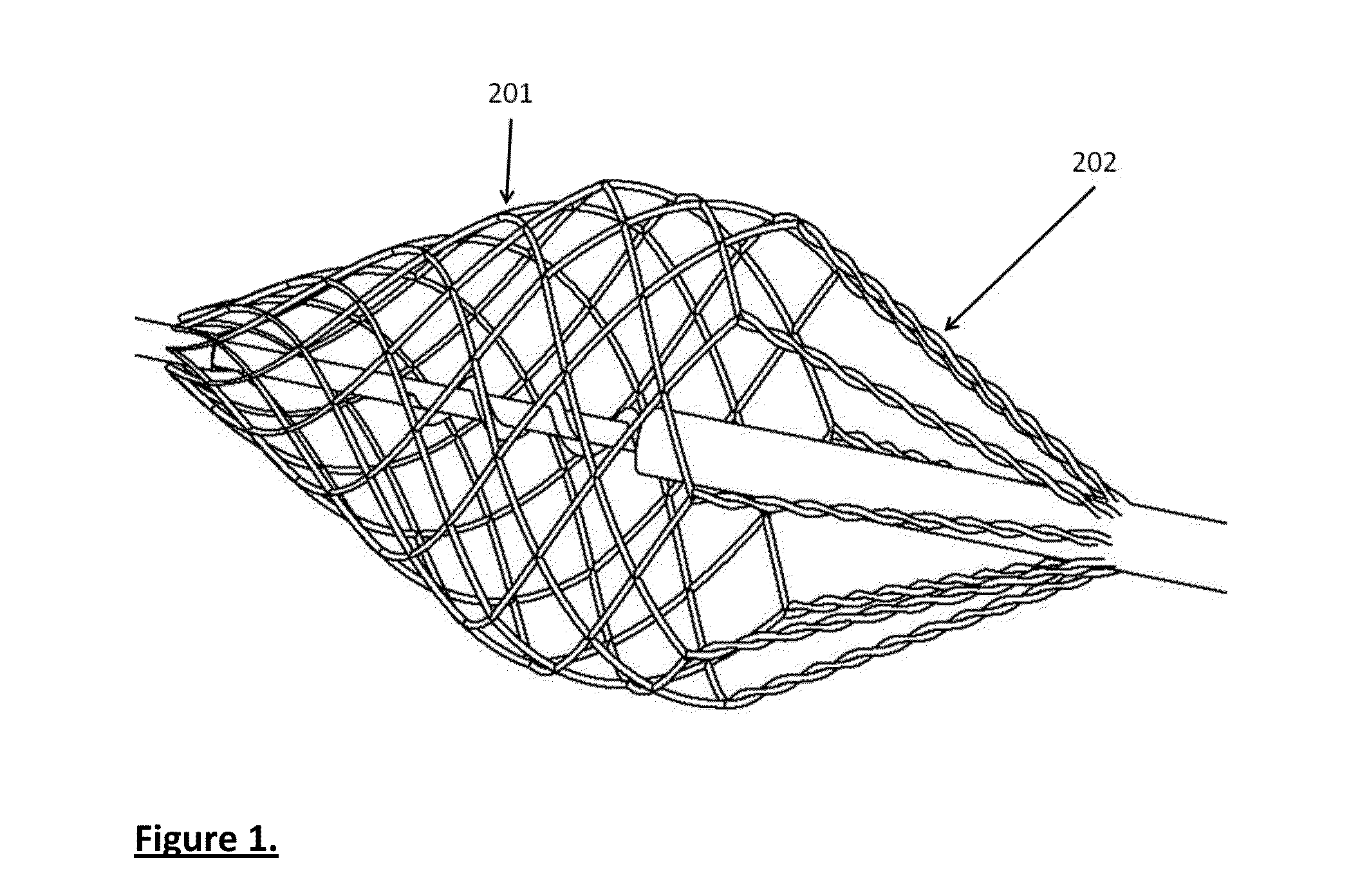
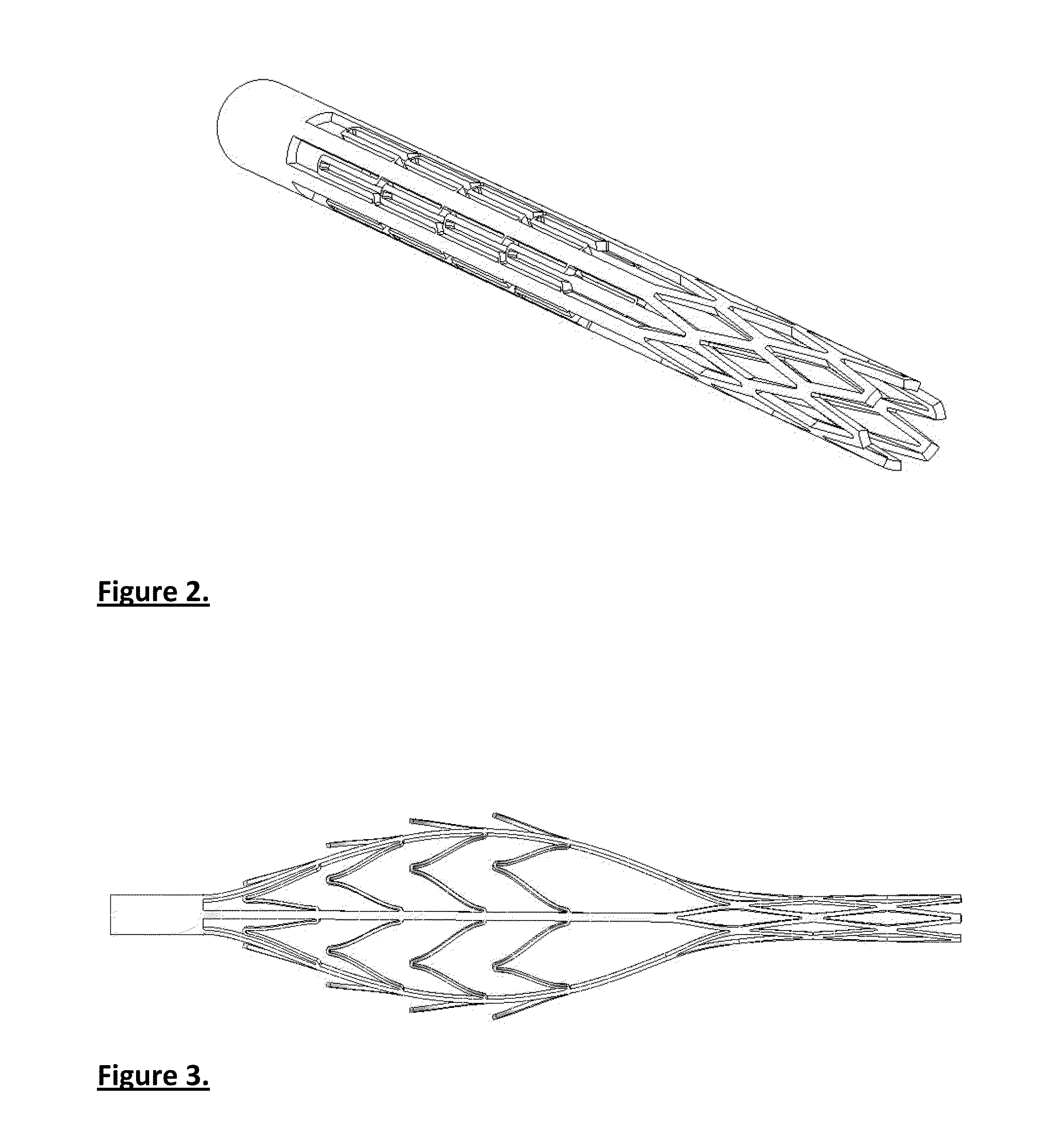
[0144]The cage can be made in many different ways, such as from a braid, a series of wires, laser cut tubes or a combination of them. The cage also may act as a filter or be a structure for the filter at the distal part. The cage can be made of different materials such as, but not limited to, polymeric, metal such as stainless steel Nitinol or cobalt chromium, or ceramic; or a combination of these materials. The proximal side of the cage is generally open and allows thrombus into the cage. The distal part of the cage is suitably constrained onto a tube or wire with small diameter and the proximal part of the cage is connected to a tube with larger diameter. A sheath may cover the entire device at delivery and at retrieval.

[0145]A connector, which can be a wire or tube and connects the distal end of the cage to user or controls the distal movement of the cage, is called the distal arm. Another connector, which can be a wire or tube and connects the proximal end o...


PUM


Abstract

A device suitable for use in a body lumen and comprises an elongated control member having a distal and a proximal end, and a radially expansible member disposed at or near the distal end and adapted for collection and / or shearing of matter (i.e. thrombus) from a wall of the body lumen (i.e. a vein or an artery). The radially expansible member has a proximal end and a distal end and is adjustable between a contracted orientation and an expanded orientation. The elongated control member comprising a proximal arm connected at or adjacent to the proximal end of the radially expansible member and a distal arm connected at or adjacent to the distal end of the radially expansible member such that movement of one arm relative to the other arm effects adjustment of the diameter or radial strength of the radially expansible member. The device comprises a control mechanism operatively connected to both arms and adapted to provide resistance to the movement of one arm relative to the other. The control mechanism may be a biasing means, a brake means, or both.

Description

TECHNICAL FIELD [0001]The invention relates to a device suitable for removing matter from inside the lumen and the wall of a body lumen. In particular, the invention relates to a thrombectomy device for removing thrombus from the walls of a vein or artery of a human.BACKGROUND TO THE INVENTION [0002]There have been many methods and devices to extract a blockage from vessels. Thrombectomy devices exist that macerate and extract the clot rather than pulling out the clot intact. The followings are some of the related patents.[0003]U.S. Pat. No. 5,972,019 introduces an embolism treatment device having a core element and a cage. The cage may include an expandable braid which is rotatably attached to the core element and can be opened to separate the clot from the vessel wall or be expanded beyond the clot to pull it out. The core element has a rotatable part which is non removable from the cage.[0004]U.S. Pat. No. 6,066,158 discloses an embolectomy device having a core wire element and a...

Claims


Application Information

Patent Timeline
Patent Type & Authority Applications(United States)
IPC IPC(8): A61B17/3207A61B17/221
CPCA61B17/320725A61B17/221A61B2017/2212A61B17/320783A61B17/320758A61B2017/00685A61B2017/320733A61B17/32056A61B2017/320008A61B2017/320064A61B2217/005
Inventor BRUZZI, MARKKASIRI GHAHI, SAEIDHENEGHAN, PAUL
Owner THE NAT UNIV OF IRELAND GALWAY
Learn More