
Low radial force filter

a filter and radial force technology, applied in the field of low radial force filter, can solve the problems of internal forces fatigue, difficult to remove, unintended consequences, etc., and achieve the effect of less susceptible to wear

Active Publication Date: 2016-02-11
COOK MEDICAL TECH LLC
View PDF5 Cites 19 Cited by
  • Summary
  • Abstract
  • Description
  • Claims
  • Application Information

AI Technical Summary

Benefits of technology

The present disclosure describes a filter apparatus and method of filtering with no or minimal radial force that can be easily retrieved. The filter unit exerts about zero or minimal force on the vessel wall which allows for maintained vessel flexibility and reduces the risk of fatigue. The filter may be less susceptible to wear and may be removed from the vessel wall even after endothelialization has occurred. This leads to minimal trauma to the vessel wall. Overall, the technical effects of the present invention allow for effective filtering while maintaining the natural function and flexibility of the body vessel.

Problems solved by technology

However, the literature shows that over time this force may have unintended consequences, such as tenting of the vessel walls.
Further, because typical filters may require sufficient stiffness to push on the vessel wall, they may also have internal forces pushing on other parts of the filter.
The literature suggests that over time such internal forces may fatigue.
Depending on the barbs' geometry, they may be difficult to remove after endothelialization.
It may also be difficult for the physician to tell if the barbs have penetrated through the wall.

Method used


Image

  • Low radial force filter
  • Low radial force filter
  • Low radial force filter

Examples


Embodiment Construction

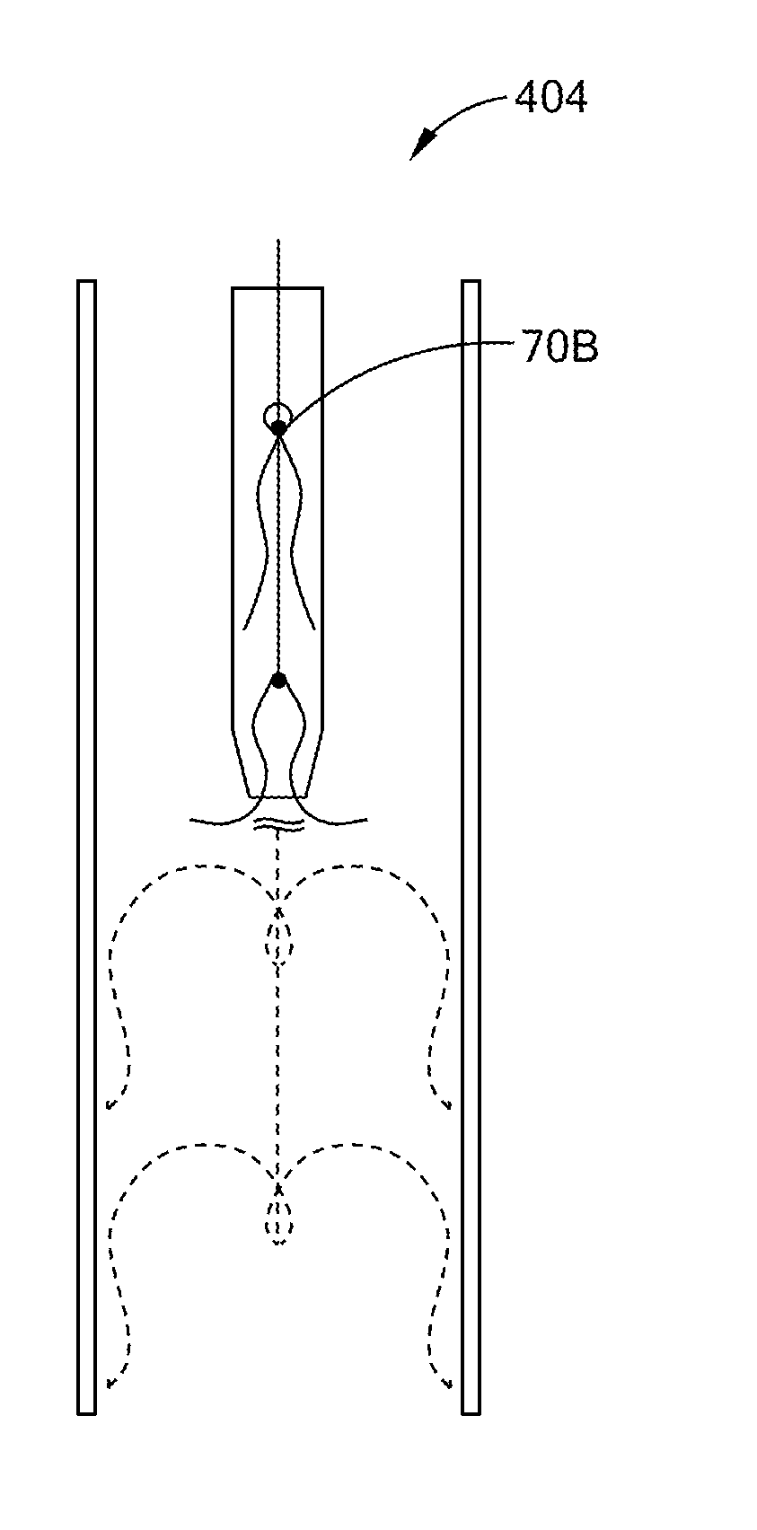
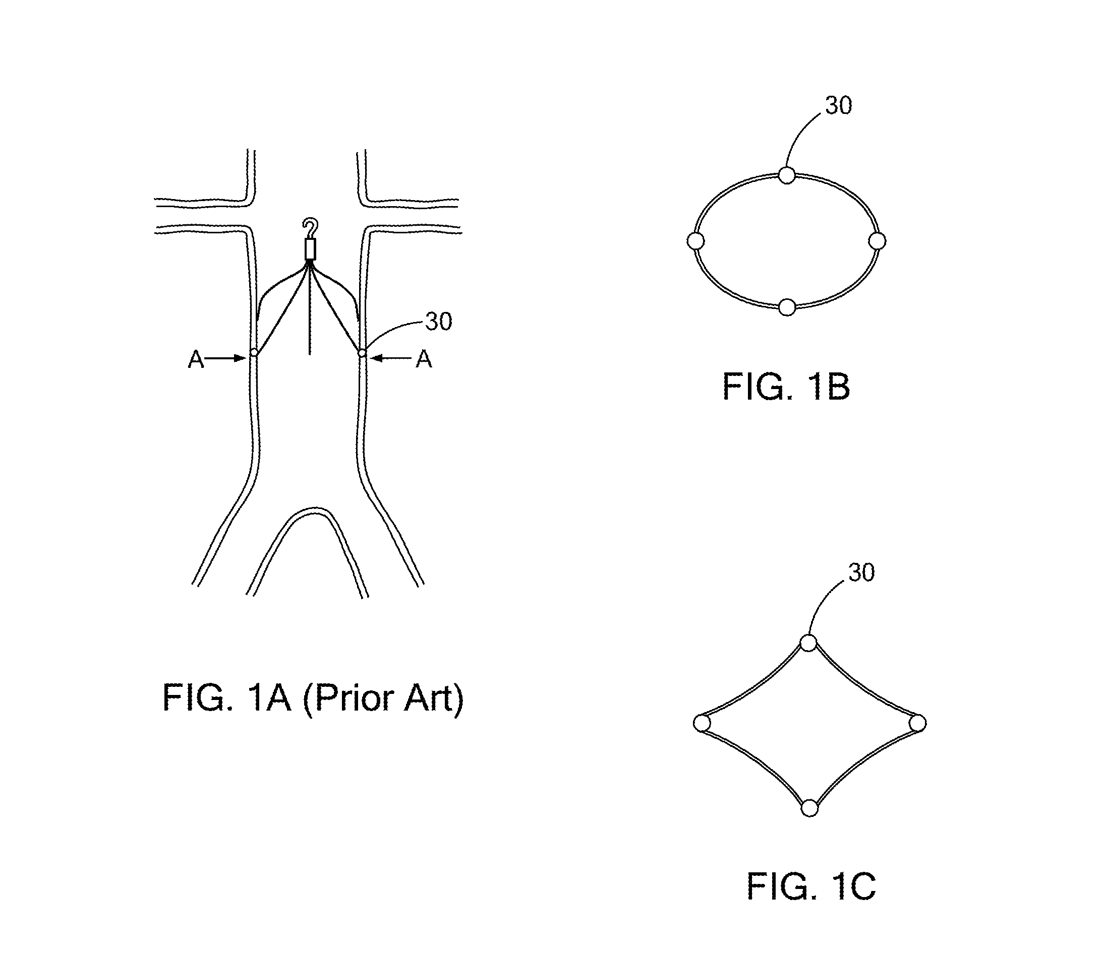
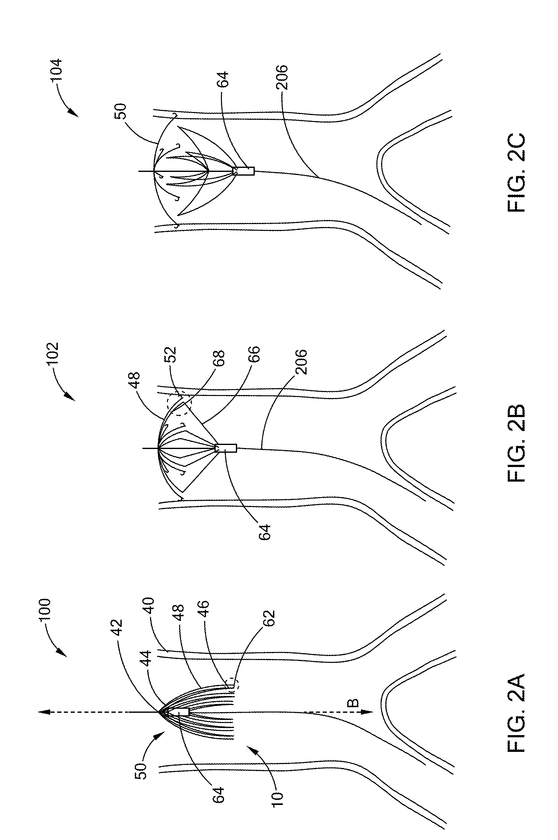
[0030]The present disclosure provides generally for examples of a method of filtering in a body vessel (i.e. vena cava), which uses a flexible filter unit. The present disclosure also provides for examples of a low radial force filter apparatus. The accompanying figures are provided for general understanding of the structure of various embodiments. However, this disclosure may be embodied in many different forms. These figures should not be construed as limiting and they are not necessarily to scale.

[0031]All publications, patent applications, patents, and other references mentioned herein are incorporated by reference in their entirety. Unless otherwise defined, all technical and scientific terms used herein have the same meaning as those commonly understood by one of ordinary skill in the art to which this disclosure pertains. In the case of conflict the present disclosure and definitions will control.

[0032]“About” or “substantially” mean that a given quantity is within 10%, prefe...


PUM


Abstract

The disclosure provides a filter apparatus and method of filtering in a body vessel. The filter apparatus comprises a filter unit and an expandable introducer designed to deliver the filter unit to the target filtering site. The filter unit attaches to the expandable introducer via a plurality of anchors on the filter unit. The expandable introducer delivers and presses the anchors to the vessel wall during implantation. After implantation, the filter unit exerts minimal or about zero radial force against the vessel wall.

Description

CROSS-REFERENCE TO RELATED APPLICATIONS[0001]This application claims priority under 35 U.S.C. §119(a) to U.S. Provisional Patent Application Ser. No. 62 / 033,826, filed Aug. 6, 2014, entitled “LOW RADIAL FORCE FILTER,” the entire contents of which are hereby incorporated by reference.BACKGROUND[0002]1. Technical Field text[0003]The present disclosure relates to medical devices. More particularly, the disclosure relates to a low radial force filter for filtering thrombi in a body vessel.[0004]2. Background Information[0005]The vena cava is the largest vein in the body. It returns deoxygenated blood to the heart. The anatomy of the vena cava is flexible, and the vena cava moves with the diaphragm as it expands and contracts during breathing. Vena cava filters are common prophylactic devices to prevent pulmonary embolisms caused by deep vein thrombosis. Such filters can be placed using minimally invasive techniques, either from the jugular or femoral vein.[0006]Current filter devices ty...

Claims


Application Information

Patent Timeline
Patent Type & Authority Applications(United States)
IPC IPC(8): A61F2/01
CPCA61F2/01A61F2002/016A61F2002/011A61F2/013A61F2220/0016A61F2230/005A61F2230/0054A61F2230/0056A61F2230/0093A61F2/011
Inventor JOHNSEN, JEPPE DUFRESNEOEHLENSCHLAEGER, BENTRASMUSSEN, ERIKHANSEN, PALLE
Owner COOK MEDICAL TECH LLC
Learn More