Mobile power supply, charging base and superimposed charging platform

Inactive Publication Date: 2016-02-11
SHENZHEN WISTEK ENERGY
View PDF5 Cites 16 Cited by
  • Summary
  • Abstract
  • Description
  • Claims
  • Application Information

AI Technical Summary

Benefits of technology

[0005]A first object of the present disclosure is to propose a mobile power supply which has a simple struct

Problems solved by technology

However, when these products cannot operate normally due to low battery, it is necessary for these products to be charged as soon as possible in order to resume normal operations.
Further, existing mobile power supplies mostly are independently charged, which represents a traditional charging manner inapplicable to simultaneous charging of a plurality of the mobile power supplies, resulting in a very low charging efficiency.
Therefore, it is difficult to meet the charging demands especially in the case that a plurality of the mobile power supplies are empty of power.
In a

Method used


Image

  • Mobile power supply, charging base and superimposed charging platform
  • Mobile power supply, charging base and superimposed charging platform
  • Mobile power supply, charging base and superimposed charging platform

Examples


Embodiment Construction

[0034]The technical solution of the present disclosure will be further described by way of embodiments below in conjunction with the accompanying drawings.

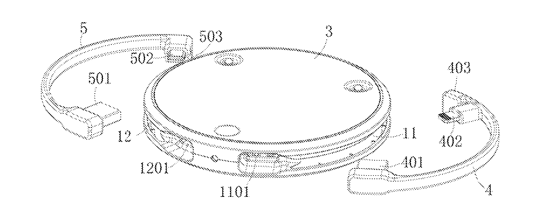
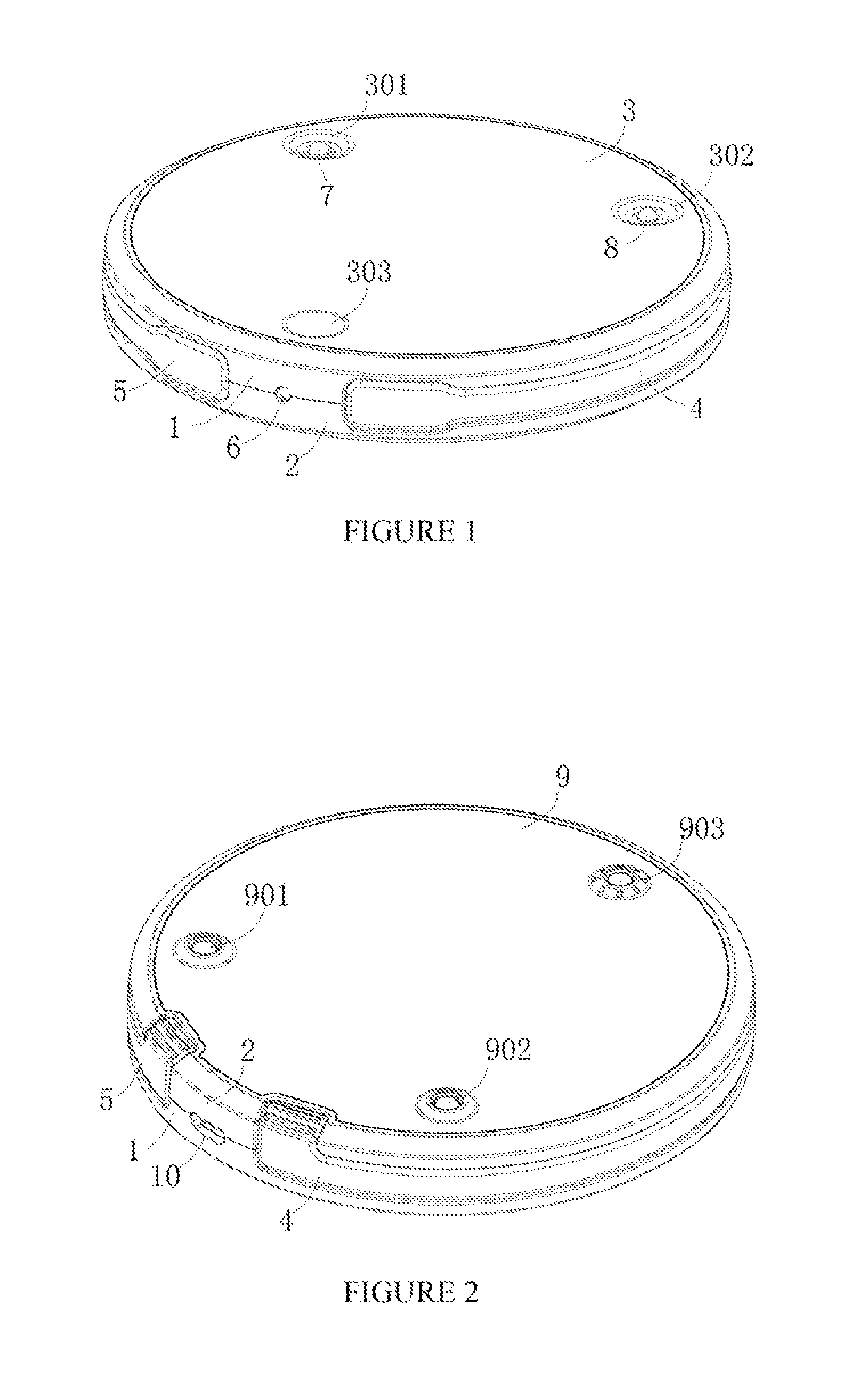
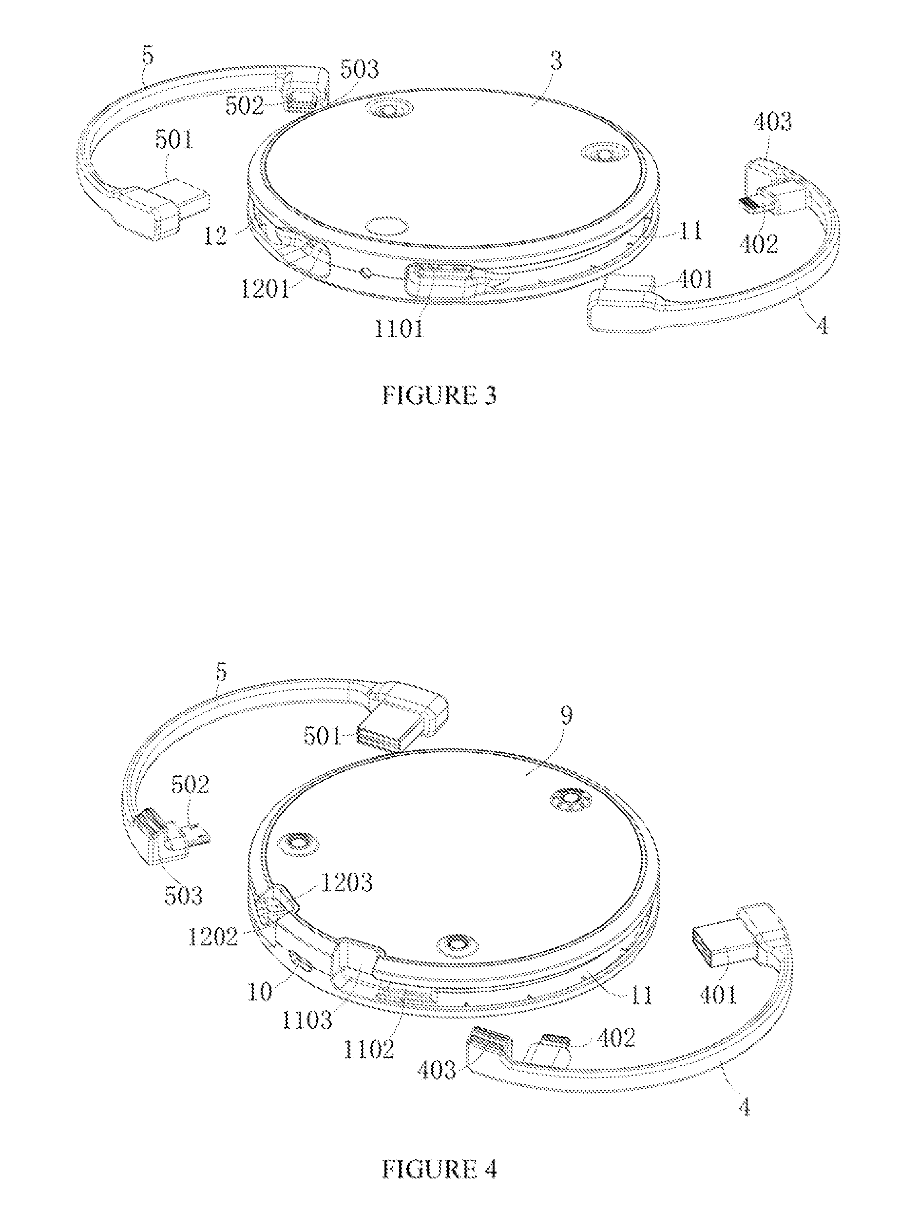
[0035]As shown in FIGS. 1 to 5, a mobile power supply includes an upper shell 1 and a lower shell 2, which are attached to each other to form a housing of the mobile power supply. A first Printed Circuit Board (PCB) 13 and a storage battery 14 connected with the first PCB 13 are disposed within the housing. An upper cover 3 is provided at the top of the upper shell 1 while a lower cover 9 is provided at the bottom of the lower shell 2. A first conductive pole 7 and a second conductive pole 8, which pass through the upper and lower covers 3 and 9 and are both connected with the first PCB 13, are vertically disposed apart from each other within the housing. The top ends of the first and second conductive poles 7 and 8 form first snap button structures (e.g. male snap button structures) with the upper cover 3, respectively, and the b...


PUM


Abstract

A mobile power supply includes an upper and lower shells, both of which are attached to each other to form a housing of the mobile power supply. A first PCB and a storage battery connected with the first PCB are disposed within the housing. An upper cover is provided at the top of the upper shell. A lower cover is provided at the bottom of the lower shell. A first and second conductive poles, which pass through the upper and lower covers and are both connected with the first PCB, are vertically disposed apart from each other within the housing. Top ends of the first and second conductive poles form first snap button structures with the upper cover, respectively. Bottom ends of the first and second conductive poles form first buckling structures with the lower cover, respectively, the first buckling structures match with the first snap button structures, respectively.

Description

CROSS-REFERENCES TO RELATED APPLICATION[0001]This application claims the priority to a Chinese patent application No, 201420444690.5 filed on Aug. 7, 2014 and entitled “MOBILE POWER SUPPLY, CHARGING BASE AND SUPERIMPOSED CHARGING PLATFORM”, which is incorporated herein by reference in its entirety.TECHNICAL FIELD [0002]The present disclosure relates to the field of mobile power supply technologies, in particular, to a mobile power supply, a charging base (i.e. a charging dock) and a superimposed charging platform.TECHNICAL BACKGROUND [0003]Digital electronic products such as mobile phones, digital cameras and palmtops have become necessities of life. However, when these products cannot operate normally due to low battery, it is necessary for these products to be charged as soon as possible in order to resume normal operations. Therefore, the battery life has attracted lots of attentions in using the digital electronic products.[0004]Further, existing mobile power supplies mostly are...

Claims


Application Information

Patent Timeline
IPC IPC(8): H02J7/00H05K7/02
CPCH05K7/02H02J7/0042H01M50/216Y02E60/10
Inventor SUN, HUI
Owner SHENZHEN WISTEK ENERGY
Why Eureka
Try Eureka