Power supply source for an electric heating system

a technology for electric heating and power supply, applied in the direction of electric heating, heating element shapes, dc-ac conversion without reversal, etc., can solve the problems of reducing the efficiency of energy conversion, unable to consider permanent mobility solutions, and discharging an unimportant portion of power, so as to increase the energy conversion factor

Inactive Publication Date: 2016-02-11
KLYOSOV VLADIMIR ALEKSEEVICH +1
View PDF12 Cites 8 Cited by
  • Summary
  • Abstract
  • Description
  • Claims
  • Application Information

AI Technical Summary

Problems solved by technology

The switch transistors operate in a rich switch mode and dissipate an unimportant portion of power, only within rather short time intervals.
However, such solutions can not be considered as “perpetuum mobile” because processes passing in it are consistent with laws of conversion and conservation of energy.
Despite plurality of known solutions, there is a problem of creation of alternative electric energy sources which realize in practice high-effective conversion of environmental force-field potential energy into electric energy.
Thus, a disadvantage of the described analogue is that a chain of energy transfer comprises a part which transfers the energy of electromagnetic field by means of inductive (transformer) coupling between two inductance coils.
It is known that a transfer of the energy (energy of electromagnetic field) by such a way is inevitably associated with some irretrievable losses due to the hysteresis phenomena and absorption of energy by other (passive) objects, located in zone of action of the electromagnetic field, which decreases the efficiency of energy conversion.
Coupling of inductance coil with a primary energy source via one of the ends of the coil limits a possible increase of the energy conversion factor.
In addition to this presence of filters and frequency controllers complicates the structure and decreases the possibilities of its practical use.
As in the previously described prior art device in this case the communication of the inductance coil with the primary energy source is carried out through one of the ends of the inductance coil, which limits possibilities of increasing of energy conversion factor.

Method used


Image

  • Power supply source for an electric heating system
  • Power supply source for an electric heating system
  • Power supply source for an electric heating system

Examples


Embodiment Construction

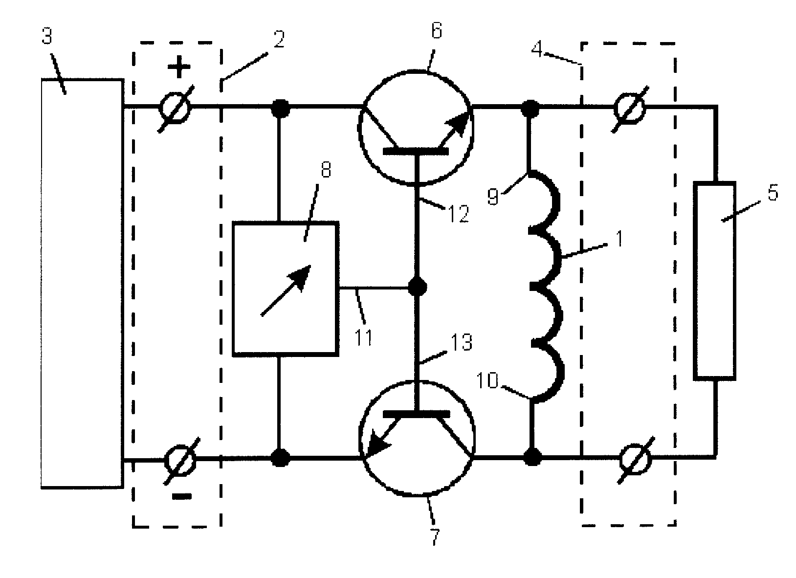
[0047]FIG. 1 shows the claimed power supply source for an electric heating system which includes an inductive coil 1, an input circuit 2 through which the inductive coil 1 is connected to an primary electric energy source 3, a load circuit 4 through which the inductive coil 1 is connected to a load 5, electronic switches 6, 7, and a generator 8 of unipolar pulses. Inductive coil 1 is connected to the primary electric energy source 3 by means of connection of its ends 9, 10 to opposite terminals (poles) of primary electric energy source 3 through electronic switches 6, 7 respectively. As an example, electronic switches 6, 7 here are shown as bipolar transistor switches which are the most preferred for the similar systems. However, electronic switches 6, 7 can be carried out as thyristors, electronic tubes or other electronic devices widely known to the persons skilled in the art. Output 11 of generator 8 of unipolar pulses is connected to inputs 12, 13 of electronic switches 6, 7 whi...


PUM


Abstract

The invention relates to power engineering, in particular to electric heating systems for residential and other buildings. The power supply source for an electric heating system comprises an inductance coil (1), which is connected to a load circuit (4) and is connected to a primary source (3) of electrical energy with the possibility of periodic connection of one of the ends of said coil (9) to one of the terminals of the primary source (3) of electrical energy via an electronic switch (6), and a generator (8) of unipolarity pulses, the output of which is connected to the input of the electronic switch (6). According to the invention, the second end (10) of the inductance coil (1) is connected to the second terminal of the primary source (3) of electrical energy via a second electronic switch (7), the input of which is connected to the output of said generator (8) of pulses of single polarity so as Co ensure synchronized operation of said electronic switches (6, 7). The result which can be achieved consists in increasing the energy conversion ratio.

Description

FIELD OF THE INVENTION[0001]The present invention relates to power engineering, in particular electric systems for residential or other buildings.BACKGROUND OF THE INVENTION[0002]In recent years the amount of electricity consciously converted into heat for domestic purposes (heating and / or hot water supplying) has considerably risen. The reason for this primarily is connected with obvious advantages of electric heating in comparison with generating of heat by direct fuel combustion. The processes of electric heating provide continuous functional abilities of equipment, stable heating parameters, a possibility of wide range of power controlling in the consumption place, as well as generality and simplicity of feeding energy carrier, high controllable heating processes and ecological purity of this process. The main component of an electric heating system is the power source expediency of using an electric heating system being determined by the electric energy conversion factor of the...

Claims


Application Information

Patent Timeline
Patent Type & Authority Applications(United States)
IPC IPC(8): H02M1/08H05B3/02
CPCH02M1/08H02M2001/0048H05B3/02H02M3/158H02M7/48H05B1/0275H05B3/44H02M1/0083Y02B70/10H05B3/0019H02M1/0048
Inventor KLYOSOV, VLADIMIR ALEKSEEVICHALEKSANDROV, SERGEY NIKKOLAEVICH
Owner KLYOSOV VLADIMIR ALEKSEEVICH
Why Eureka
Try Eureka