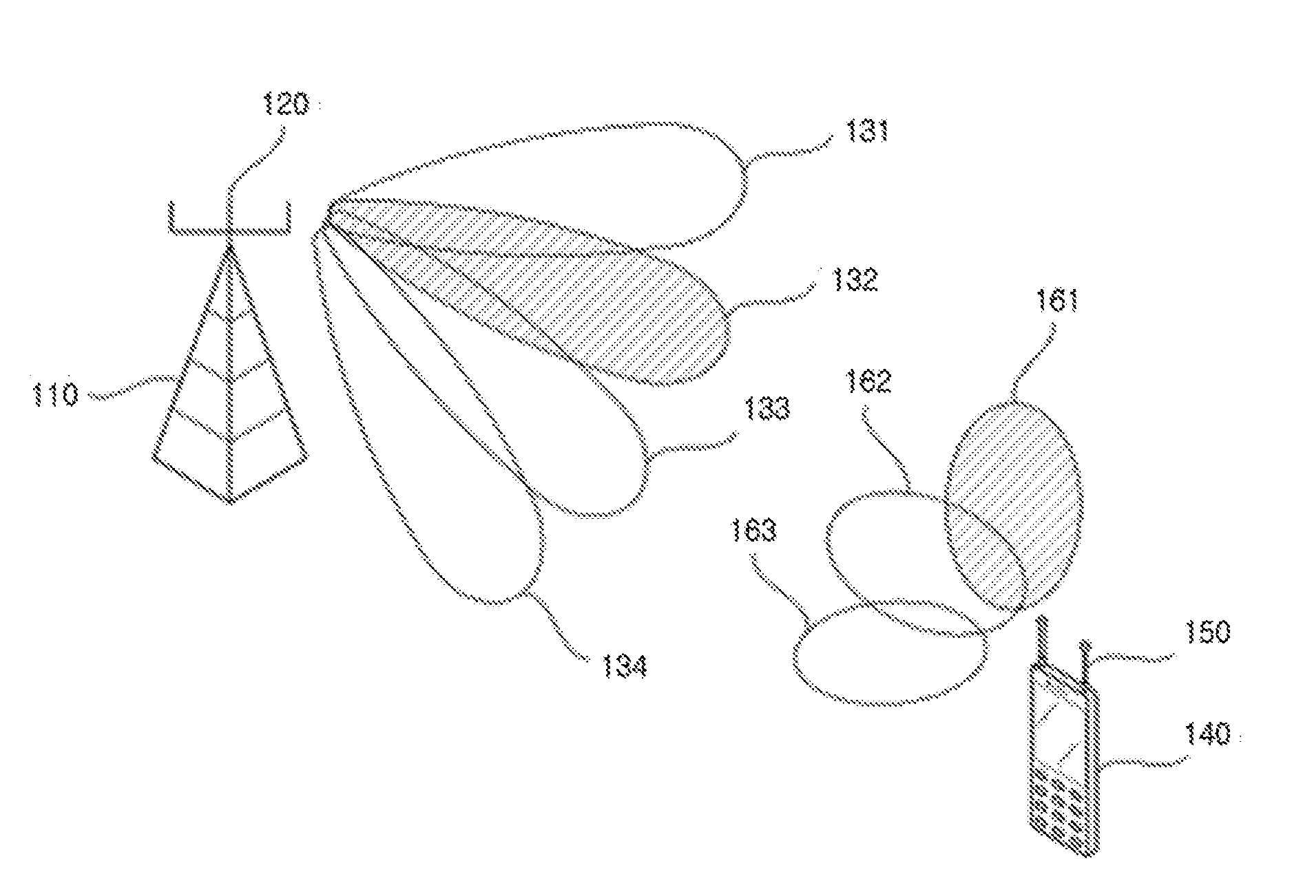
Apparatus and method for training beam

a beam and antenna technology, applied in diversity/multi-antenna systems, instruments, wireless communication, etc., can solve the problems of shortening taking a large amount of time for realizing the beam training, etc., to shorten the time taken for searching the beam effectively.

Active Publication Date: 2016-02-11
CHUNG ANG UNIV IND ACADEMIC COOP FOUND
View PDF5 Cites 70 Cited by
  • Summary
  • Abstract
  • Description
  • Claims
  • Application Information

AI Technical Summary

Benefits of technology

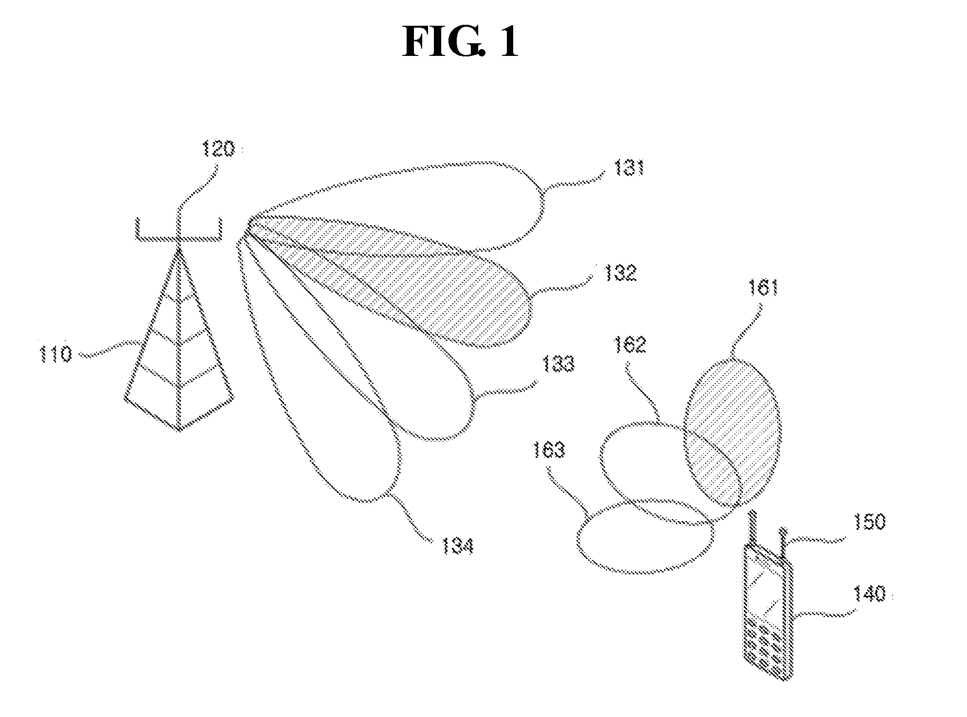
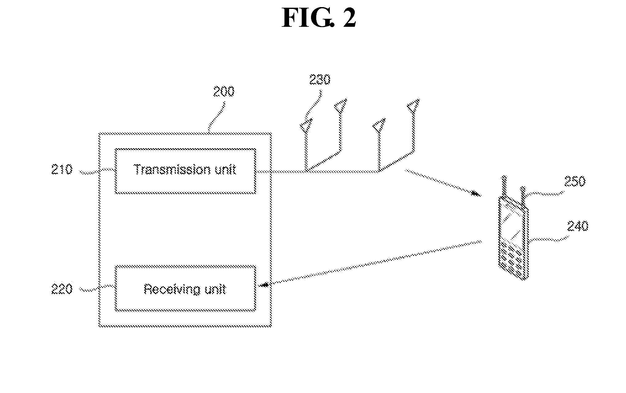
[0008]One embodiment of the invention provides a method of performing rapidly synchronization and beam training between a transmitter using a transmission array and a receiver using a receiving array.
[0011]Still another embodiment of the invention provides to a method of searching effectively the beam.
[0012]Still another embodiment of the invention provides to a method of shortening a time taken for searching the beam.
[0050]A method according to one embodiment of the invention may perform rapidly synchronization and beam training between a transmitter using a transmission array and a receiver using a receiving array.
[0054]The method may shorten a time taken for searching the beam.

Problems solved by technology

Specially, in the event that a lot of beams exist, much amount of time is taken for realizing the beam training.
The method may shorten a time taken for searching the beam.

Method used


Image

  • Apparatus and method for training beam
  • Apparatus and method for training beam
  • Apparatus and method for training beam

Examples


embodiment 1

[0226]1) Embodiment 1 of Transmitting the ID Using a Gold Sequence

[0227]In one embodiment, the transmission unit 1110 may generate the gold sequence based on the ID of the transmission training beam and the ID of the training sub array according to following equation 28, and transmit the generated gold sequence to the receiver 1170.

Bng(k)=x1(k+n)mod N+x2(k+n+s)mod N  [Equation 28]

[0228]Here, Bng(k) indicates the generated gold sequence. k means an index of a subcarrier in which the gold sequence is modulated, and k=0, 1, . . . , N−1. n=0, 1, . . . , NID−1. N indicates a length of the gold sequence. r1,r2 mean different m sequences having a length of N. N is a parameter for separating IDs of cells by cyclic-shifting a beam ID preamble in frequency domain. NID is total number of the IDs of the cells. S is a parameter for determining the gold sequence, and s=aAST+b. a and b are parameters for separating the ID of the training sub array from the ID of the transmission training beam, a=0...

embodiment 2

[0229]2) Embodiment 2 of Transmitting the ID Using a Gold Sequence

[0230]In one embodiment, the transmission unit 1110 may generate the gold sequence based on the ID of the transmission training beam according to following equation 29, and map the generated gold sequence with certain interval in frequency domain according to the ID of the training sub array. The transmission unit 1110 may transmit the mapped gold sequence to the receiver 1170.

Bnb(m)=x1(m+m)mod N+x2(m+n+b)mod N  [Equation 29]

[0231]Here, Bnb(m) is the generated gold sequence. r1,r2 are different m sequences having a length of N. m is a sequence index, and m=0, 1, . . . , NS−1. n is a parameter for separating IDs of cells, and n=0, 1, . . . , NID−1. a and b are parameters for separating the ID of the training sub array from the ID of the transmission training beam, a=0, 1, . . . , Asr−1, and b=0, 1, . . . , BID−1. Idx means an index of a subcarrier mapped in frequency domain, and Idx=mAsr+a.

[0232]Referring to the embodi...


PUM


Abstract

A system for training beam including a transmitter forming a transmission beam using a transmission array and a receiver forming a receiving beam using a receiving array is disclosed. The transmitter transmits an identifier of a transmission training beam selected from the transmission beams using a secondary synchronization signal or a common reference signal, etc. The identifier of the transmission training beam is used for the beam training.

Description

CROSS REFERENCE TO RELATED APPLICATIONS[0001]This application is a continuation application of International Application No. PCT / KR2013 / 011417 filed on Dec. 10, 2013, which claims priority to Korean Application No. 10-2013-0075723 filed on Jun. 28, 2013 and Korean Application No. 10-2013-0120578 filed on Oct. 10, 2013. The applications are incorporated herein by reference.TECHNICAL FIELD[0002]The present disclosure relates to a technique for training a beam in an array antenna system, more particularly relates to a technique for training rapidly a pair of optimal beams including a beam in transmitter side and a beam in receiver side.[0003]The present disclosure relates to an apparatus and a method of transmitting an ID of a beam, more particularly relates to an apparatus and a method of transmitting an OFDM symbol including information concerning an ID of a beam so that the ID of the beam can be detected on a physical layer.BACKGROUND ART[0004]A radio wave in dozens of giga herz of ...

Claims


Application Information

Patent Timeline
Patent Type & Authority Applications(United States)
IPC IPC(8): H04B7/04
CPCH04B7/04H04L5/0051H04L27/2613H04B7/0408H04B7/0617H04B7/0851H01Q3/24H04B7/0626H04B7/063H04B7/0634H04B7/0639H04B7/0695H04B7/088H04W72/046H04B7/0684
Inventor CHO, YONG SOOKU, BON WOO
Owner CHUNG ANG UNIV IND ACADEMIC COOP FOUND
Why Eureka
Try Eureka