Method for synchronizing a first clock to a second clock, processing unit and synchronization system

a synchronization system and a processing unit technology, applied in multiplex communication, generating/distributing signals, instruments, etc., can solve the problems of not always being able to satisfy the synchronization accuracy, and achieve the effect of improving the synchronization accuracy and no time wasted

Inactive Publication Date: 2007-03-13
RPX CORP
View PDF8 Cites 29 Cited by
  • Summary
  • Abstract
  • Description
  • Claims
  • Application Information

AI Technical Summary

Benefits of technology

[0022]In a more general preferred embodiment of the invention, the timestamps that are to be transmitted by the processing unit to the reference clock indicate their expected time of transmission and are included in synchronization messages that are assembled in advance. These synchronization messages can then be transmitted as soon as a triggering clock pulse is received by the processing unit from the first clock. The expected time of transmission is therefore the point of time of the next clock pulse to be received from the first clock, which is supposed to be known.
[0023]There are a variety of possibilities for the processing unit of knowing the time of the next clock pulse to be received from the first clock. For example, the interval between the clock pulses received from the first clock can be known at the processing unit. The time of reception of the triggering clock pulse can then be determined in the processing unit based on the number of intervals between some starting point and the triggering clock pulse or based on a stored point of time indicating the time of reception of the last clock pulse to which one time interval is added. Any further alternative can be employed just the same.
[0024]In any case, the best clock information available in the processing unit, i.e. the clock information of the first clock, is used for timestamp creation and no time is wasted creating the packet after the triggering clock pulse; thus this approach makes the synchronization faster compared to an assembling after the triggering clock pulse and further improves the accuracy of the synchronization.
[0025]A timestamp indicating the point of time of transmission of a synchronization message by the processing unit is formed preferably from the sum of a predetermined starting time and the time interval between pulses received at the processing unit from the first clock multiplied by the number of pulses received since the starting time. Optionally, a change of offset determined after the most recent correction message, which change of offset has not been conveyed to the first clock yet, can be added to the sum, which makes the timestamp even more exact.
[0026]For the further exchange of timestamps that are to enable a determination of an offset between the first clock and the reference clock and therefrom of a correction message for the first clock, the reference clock preferably transmits upon receipt of the synchronization message from the processing unit a response message to the processing unit. This response message can in particular include the timestamp received in the synchronization message, a timestamp indicating the point of time at which the synchronization message was received at the reference clock and a timestamp indicating the point of time at which the response message is transmitted by the reference clock. The processing unit moreover determines a fourth timestamp which indicates the point of time of receipt of the response message based at least primarily on the latest clock pulse (cclk) received from the first clock. In addition, it can be based secondarily on an internal clock of the processing unit. Finally, the processing unit can generate a correction message based on the timestamp information e.g. using the NTP method described in above mentioned Internet draft RFC-1305. In particular, the correction message can be based on a frequency offset determined based on these timestamps.
[0027]It is to be noted that a correction message does not have to be generated based on every single exchange of timestamps. NTP implementations, e.g., regularly employ filters that filter out most of the exchanged synchronization messages. Actually, a reasonably long time with a big number of synchronization messages is needed to generate an accurate offset. Therefore, a correction message can be generated for example each time when the timestamp method produced the latest measured offset.

Problems solved by technology

It is not always possible, though, to implement an NTP client in the element with a clock that is to be synchronized.
However, such a processing unit may constitute a weak link in the connection between the clock that is to be synchronized and the reference clock, e.g. if the processing unit is an element with a clock that is less accurate than the clock which is to be synchronized.
For many applications, therefore, such a proceeding does not lead to a satisfying accuracy of synchronization.

Method used


Image

  • Method for synchronizing a first clock to a second clock, processing unit and synchronization system
  • Method for synchronizing a first clock to a second clock, processing unit and synchronization system
  • Method for synchronizing a first clock to a second clock, processing unit and synchronization system

Examples


Embodiment Construction

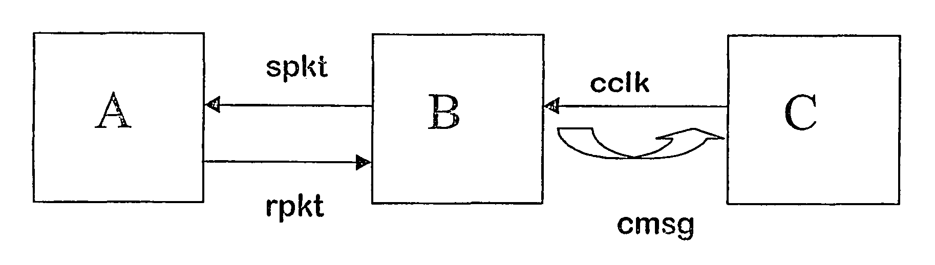
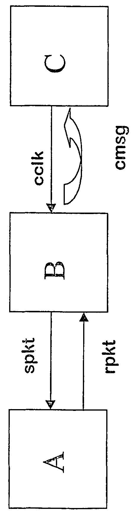
[0033]The synchronization system that is shown schematically in the figure is composed of a first element A with a first clock, a second element B with a second clock and a third element C with a third clock. The second element B is located between the first and the second element A, C and interconnects them. The data link between elements A and B does not have to be synchronous. The link can therefore be for example an IP link.

[0034]The first element A is an NTP server anywhere in the synchronization system, and the included first clock is to be used as reference clock in the system. The first element A can be for example arranged in a base station of a cellular communications network and the included first clock can be an accurate clock based on a GPS device. The second element B is a general-purpose processor based device, e.g. a PC, used as a BTS transmission unit of a second BTS site, the clock of which is rather inaccurate. The second element B includes an implementation of an...


PUM


Abstract

The invention relates to a method for synchronizing a first clock C to a reference clock A, the first clock C being connected to said reference clock A via a processing unit B. The invention moreover relates to a processing unit B and to a synchronization system. In order to enable a synchronization of said first clock C to said reference clock A via said processing, unti B. it is proposed that the processing unit B generates a correction message cmsg for the first clock C based on timestamps exchanged between the processing unit B and the reference clock A, which exchanged of timestamps is triggered by clock pulses cclk received in the processing unit B from the first clock C.

Description

FIELD OF THE INVENTION[0001]The invention relates to a method for synchronizing a first clock to a reference clock. The invention equally relates to a processing unit and a synchronization system including a first clock connected via a processing unit to a reference clock.BACKGROUND OF THE INVENTION[0002]A possibility of synchronizing a first clock to a reference clock used as an accurate time server can constitute an important feature in a variety of systems, in particular in systems in which several clocks have to work synchronously.[0003]A known and accurate method for synchronizing a first clock to a second clock is based on the network time protocol (NTP). A calculation of offsets between two different clocks based on NTP is described for example by David L. Mills in: “Internet Time Synchronization: the Network Time Protocol”, IEEE Trans. Communications 39, 10 (October 1991), 1482–1493. The Network Time Protocol and related nomenclature is also described in the Internet draft b...

Claims


Application Information

Patent Timeline
Patent Type & Authority Patents(United States)
IPC IPC(8): H04J3/06G06F1/14
CPCG06F1/14H04J3/0667H04J3/0673
Inventor PURHO, JUHA
Owner RPX CORP
Why Eureka
Try Eureka