Telemetry system with authentication

Inactive Publication Date: 2007-05-29
PARTYKA ANDRZEJ
View PDF74 Cites 28 Cited by
  • Summary
  • Abstract
  • Description
  • Claims
  • Application Information

AI Technical Summary

Benefits of technology

[0007]Some embodiments of the present invention comprise a frequency hopping receiver that rapidly acquires and maintains synchronization with a plurality of intermittently transmitting frequency hopping transmitters, which enables the transmitters to omit the transmission of long preambles. This is advantageous because it lowers the average current drain in the transmitters and, consequently, lengthens their battery life. Furthermore, some embodiments of the present invention are advantageous in that they provide improved reliability

Problems solved by technology

Second, short and infrequent transmissions lower the probability that the data is lost due to collisions that occur when two or more transmitters transmit at the same time.
Typically, such systems transmit data at a single frequency, and thus are susceptible to interference and signal loss due to phenomena known as “multipath fading.” Consequently, the reliability of such systems is compromised or, conversely, the transmitted power has to be increased to overcome the fading, which results in larger power drain and shorter battery life.
Besides, there usually are regulatory limits that restrict such transmitter power and thus limit the possible compensation by sheer increase of power.
However, frequency hopping systems require a long acquisition time and they are typically used in two way communication applications in which all the devices are continuously synchronizing with one master device or with each other using a variety of synchronization methods as

Method used


Image

  • Telemetry system with authentication
  • Telemetry system with authentication
  • Telemetry system with authentication

Examples


Example

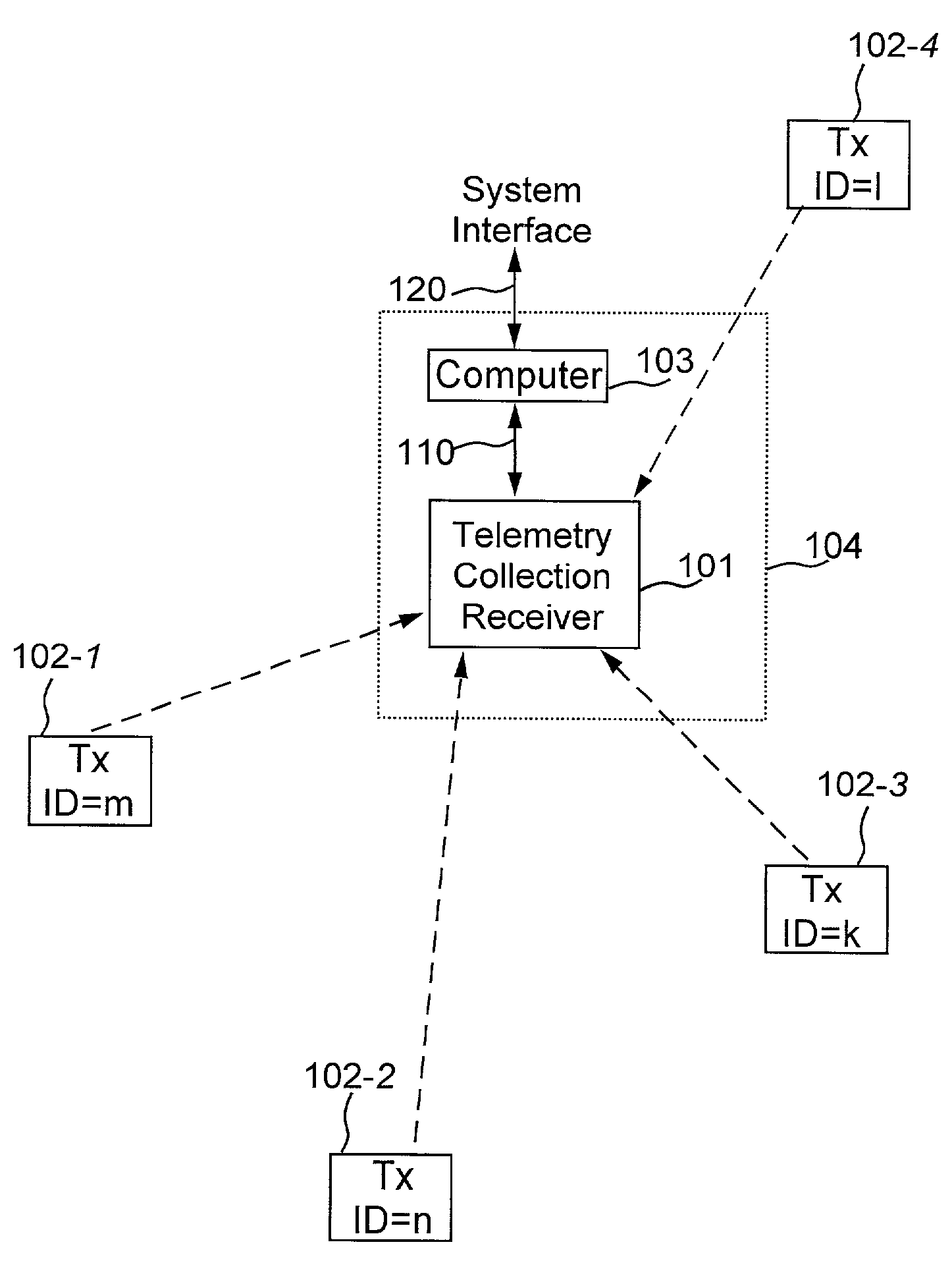
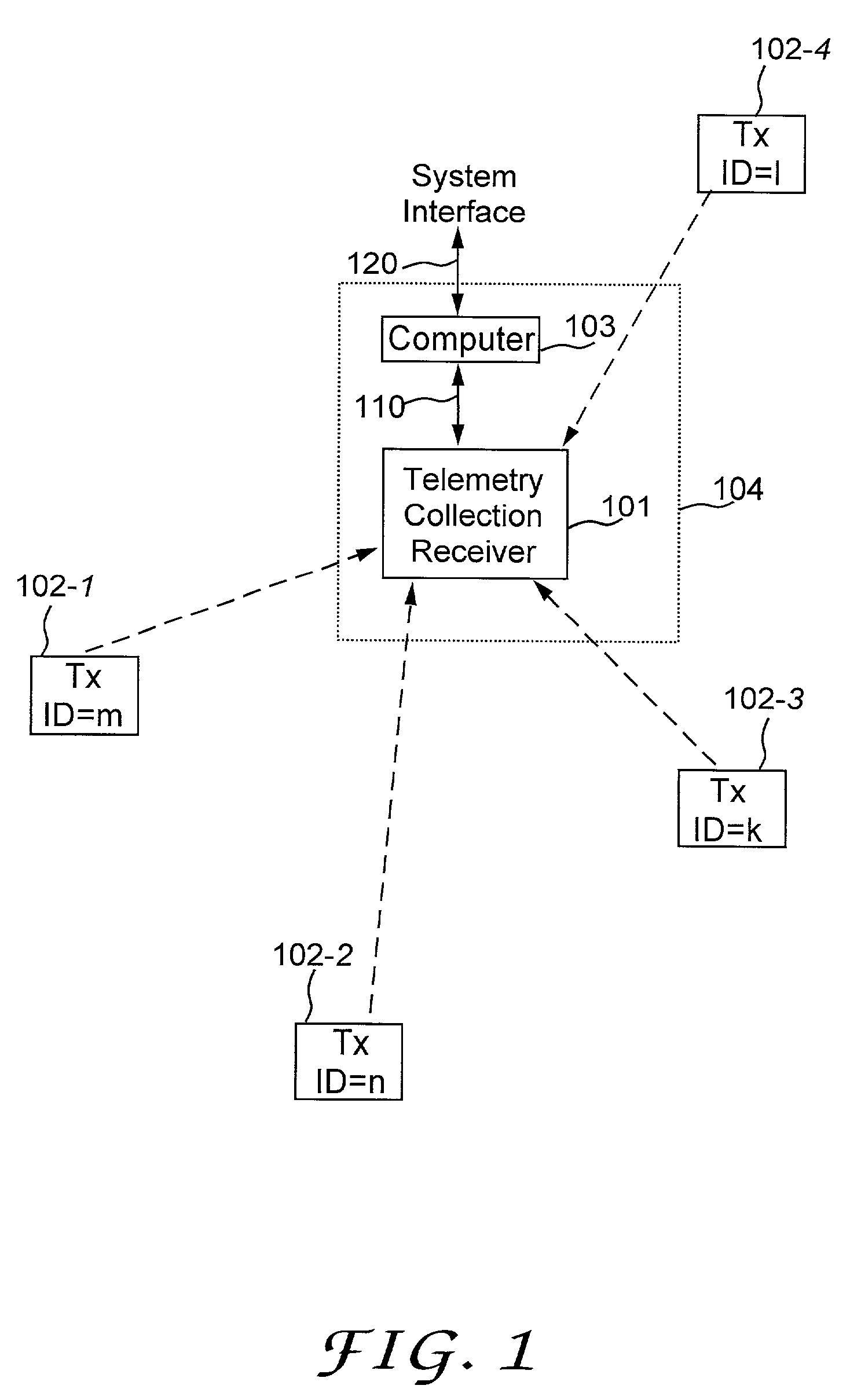
[0021]Referring to FIG. 1, the frequency hopping system includes a telemetry collection unit 104 and a plurality of remote telemetry transmitters (transmitters) 102-1, 102-2, 102-3 and 102-4. The telemetry collection unit includes a telemetry collection receiver (receiver) 101, and a computer 103 that can communicate the telemetry over system interface 120. The receiver 101 includes a receiver interface 110 through which the receiver can be connected, locally or remotely, to a variety of interface equipment, a controller, or a computer. Each remote telemetry transmitter includes an interface or a sensor or an operation to be monitored. Each remote telemetry transmitter intermittently transmits short messages to the telemetry collection receiver. The remote telemetry transmitters are not connected to each other and do not receive messages back from the telemetry collection receiver. The remote telemetry transmitters transmit messages when they need to without any regard to other remo...


PUM


Abstract

A telemetry system includes many radio transmitters using frequency hopping carriers to intermittently transmit transmissions indicative of status of sensors associated with the transmitters. The transmitters transmit transmissions independently of a receiver receiving the transmissions and independently of each other. The carrier frequency and the time between transmissions are changed according to a frequency-time hopping sequence that is different for each transmitter. The sequences and the resulting frequency ad time hopping are predictable and can be reproduced in the receiver based on the transmitter ID number. The system also includes one or more receivers containing a plurality of memory registers to hold, simultaneously for each transmitter, digital data indicative of (a) expected time and (b) expected frequency of the next transmission occurrence. The data is updated based on the time and the content of the received transmissions. The receiver authenticates the received transmissions by discriminating transmissions received at a wrong frequency and time. In addition, each transmitter encrypts the transmission using a variable encryption key that is varied with each transmission. The key variations are based on the frequency and time hopping sequence and are different for each transmitter. Alternatively, prior to encryption, each transmitter modifies data for transmission, using a modifier that is varied based on the frequency and time hopping sequence that is different for each transmitter. In addition, for faster acquisition and robust operation, the receiver includes and RSSI circuit based on FFT to detect transmitted carrier power at several different frequencies. The receiver also includes one or more frequency selective circuits that are tuned in response to the outputs from FFT and the status of the time and frequency registers.

Description

CROSS-REFERENCE TO RELATED APPLICATIONS[0001]This application claims the benefit, and is a continuation-in-part of, U.S. application Ser. No. 09 / 067,859, filed on Apr. 9, 1998, and entitled “Frequency Hopping System for Intermittent Transmission with Receiver Using Individual Tracking, FFT, and Authentication, now U.S. Patent No. 6,188,715.FIELD OF THE INVENTION[0002]The present invention relates to telemetry in general, and, more particularly, to a system in which a plurality of transmitters intermittently transmit short messages indicative of status of sensors associated with the transmitters, to a method of synchronization suitable for using frequency hopping carrier in such systems, and to a method of authentication of the received messages.BACKGROUND OF THE INVENTION[0003]Some wireless telemetry systems (e.g., burglar alarms, fire alarms, power utility meters, leak detectors, environmental monitoring, etc.) comprise many transmitters that periodically or sporadically transmit m...

Claims


Application Information

Patent Timeline
IPC IPC(8): H04B1/00H04B1/713
CPCH04B1/7156H04B2001/71367H04B2001/71566H04K1/00H04K3/25H04K3/65H04K3/827H04K3/88H04L27/30
Inventor PARTYKA, ANDRZEJ
Owner PARTYKA ANDRZEJ
Why Eureka
Try Eureka