High-speed internal clock synchronizing method and circuit

a high-speed, internal clock technology, applied in the direction of digital transmission, generating/distributing signals, instruments, etc., can solve the problems of slow operation speed, difficult to establish accurate synchronization depending on external reset timings, and inability to achieve smooth data exchange between

Inactive Publication Date: 2000-02-01
MITSUBISHI ELECTRIC CORP
View PDF6 Cites 27 Cited by
  • Summary
  • Abstract
  • Description
  • Claims
  • Application Information

AI Technical Summary

Benefits of technology

Another object of the present invention is to provide an internal clock synchronizing circuit capable of achieving the synchronization of the internal clock signals quickly with a simple circuit configuration.
The clock generator, receiving the synchronizing control bit set in the control register, may increase a dividing ratio of the original clock signal to reduce a frequency of its internal clock signal, when the synchronizing control bit indicates that synchronization of the internal clock signal with the reference clock signal is to be carried out.

Problems solved by technology

This is because the system component circuits are operating in synchronism with each other, and hence if their internal clock signals are brought out of synchronization, they cannot achieve smooth data exchange between them, which may lead to an erroneous operation.
Moreover, although clock generators of the system component circuits are conventionally synchronized with each other through an external reset or interrupt, the trend of devices toward a faster operating speed makes it difficult to establish accurate synchronization depending on the external reset timings.
Although the conventional internal clock synchronizing circuit with such an arrangement can achieve the synchronization of the internal clock signals (divided clock signals) between the system component circuits (microprocessors), it has a drawback that it takes a rather long time to establish the synchronization because it integrates the phase compared result, and then compares the integral results by the comparator to suspend the original clock signal.
This present a problem of delaying the response in today's high speed microprocessors.

Method used


Image

  • High-speed internal clock synchronizing method and circuit
  • High-speed internal clock synchronizing method and circuit
  • High-speed internal clock synchronizing method and circuit

Examples


embodiment 1

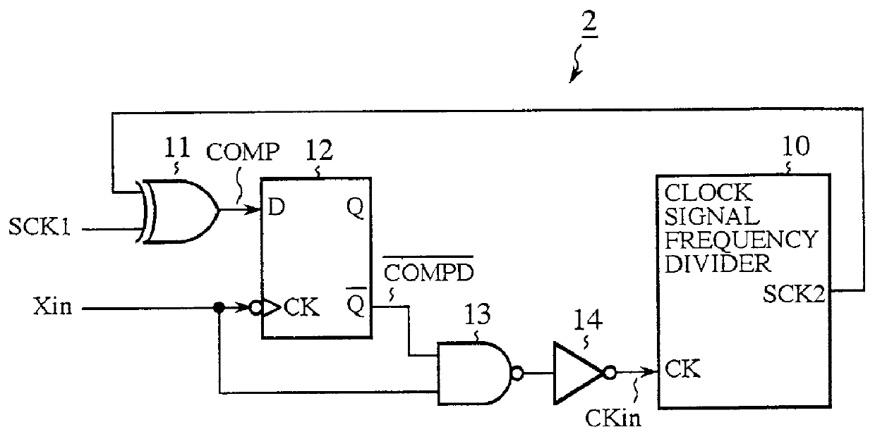
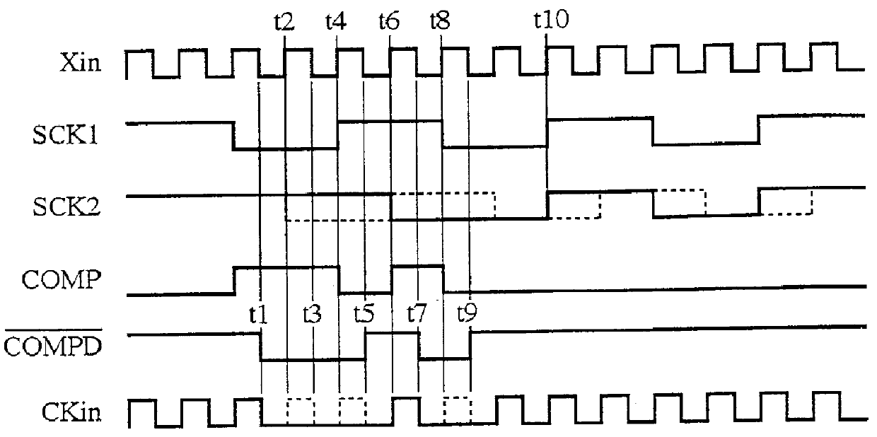
FIG. 1 is a block diagram showing an internal clock synchronizing circuit in accordance with the present invention, and FIGS. 2A and 2B are block diagrams each showing a configuration of a system to which an internal clock synchronizing method in accordance with the present invention is applied. Here, FIG. 2A shows a system comprising two system component circuits, and FIG. 2B shows a system including three system component circuits.

In FIGS. 2A and 2B, reference numerals 1a, 1b and 1c each designate an IC (integrated circuit) chip as a system component circuit constituting the systems, and reference numerals 2's each designate an internal clock synchronizing circuit which is placed in the IC chips 1b and 1c, and has a configuration as shown in FIG. 1. Here, the IC chip 1a functions as a master system component circuit that divides an original clock signal Xin of the system to generate an internal clock signal SCK1, and outputs the internal clock signal SCK1 as a reference clock sign...

embodiment 2

Although the synchronization of the internal clock signals is carried out without exception in the foregoing embodiment 1, it can be modified to be performed as needed. FIG. 4 is a block diagram showing an embodiment 2 of such an internal clock synchronizing circuit in accordance with the present invention. In FIG. 4, the same reference numerals as those of FIG. 1 designate the corresponding portions, and the description thereof is omitted here.

In FIG. 4, the reference numeral 15 designates a control register in which a synchronizing control bit is set to indicate whether or not the internal clock signal SCK2 generated by the clock signal frequency divider 10 should be synchronized with the reference clock signal SCK1. The reference numeral 16 designates an NAND circuit for controlling, in response to the synchronizing control bit set in the control register 15, whether to supply or not the NAND circuit 13 with the compared result signal COMPD fed from the Q terminal of the D flip-f...

embodiment 3

Although the foregoing embodiment 1 does not comprise an indicator for showing whether the internal clock synchronizing circuit is carrying out the synchronizing operation or not, it can be provided. FIG. 5 is a block diagram showing an embodiment 3 of such an internal clock synchronizing circuit in accordance with the present invention, in which the corresponding portions to those of FIG. 1 are designated by the same reference numerals. In FIG. 5, the reference numeral 17 designates a flag bit for indicating whether the internal clock synchronizing circuit is carrying out the synchronizing operation or not.

Next, the operation of the present embodiment 3 will be described.

Since the synchronizing operation for synchronizing the internal clock signal SCK2 to the reference clock signal SCK1 is the same as that of the embodiment 1, the description thereof is omitted here. The D flip-flop 12 holds the compared result signal COMP fed from the exclusive OR circuit 11 in synchronism with th...


PUM


Abstract

An internal clock synchronizing circuit capable of solving a problem involved in a conventional high speed microcomputer system in that it takes a long time to establish clock synchronization between system component circuits of the microcomputer system. The internal clock synchronizing circuit includes a clock generator for generating an internal clock signal by dividing an original clock signal; a clock comparator for comparing the internal clock signal with a reference clock signal; a compared result holding circuit for holding, in synchronism with the original clock signal, a compared result signal output from the clock comparator; and a clock switching circuit for switching supply of the original clock signal to the clock generator in response to the compared result signal held in the compared result holding circuit.

Description

1. Field of the InventionThe present invention relates to an internal clock synchronizing method and circuit for synchronizing the internal clock signals used in a plurality of system component circuits constituting a system.2. Description of Related ArtIt is often necessary for a conventional system constructed by combining a plurality of system component circuits to synchronize their internal clock signals with each other. This is because the system component circuits are operating in synchronism with each other, and hence if their internal clock signals are brought out of synchronization, they cannot achieve smooth data exchange between them, which may lead to an erroneous operation.Furthermore, to keep with the present trend to lower power consumption, the system component circuits are often provided with a function of reducing current consumption by halting their internal clock signals while they are inactive. This makes it necessary for these circuits to synchronize their inte...

Claims


Application Information

Patent Timeline
Patent Type & Authority Patents(United States)
IPC IPC(8): G06F1/10H03L7/085H03L7/08H03L7/099H04L7/00G06F15/16G06F1/12G06F15/177H03L7/00H04L7/033
CPCG06F1/10H03L7/085H03L7/0993H04L7/0008H04L7/0276G06F1/12
Inventor YAMASAKI, TAKASHI
Owner MITSUBISHI ELECTRIC CORP
Why Eureka
Try Eureka