Scanner and method for performing exposure process on wafer

Inactive Publication Date: 2016-02-18
MACRONIX INT CO LTD
View PDF8 Cites 7 Cited by
  • Summary
  • Abstract
  • Description
  • Claims
  • Application Information

AI Technical Summary

Benefits of technology

[0008]Accordingly, the present invention is directed to a scanner and a method for performing an exposure pr

Problems solved by technology

However, sometimes the actual position of the current layer formed on the wafer is not the desired position.
However, non-ideal temperature, non-ideal vacuum pressure, stresses of films, and other factors of the process ca

Method used


Image

  • Scanner and method for performing exposure process on wafer
  • Scanner and method for performing exposure process on wafer
  • Scanner and method for performing exposure process on wafer

Examples


Example

[0021]Reference will now be made in detail to the present embodiments of the invention, examples of which are illustrated in the accompanying drawings. Wherever possible, the same reference numbers are used in the drawings and the description to refer to the same or like parts.

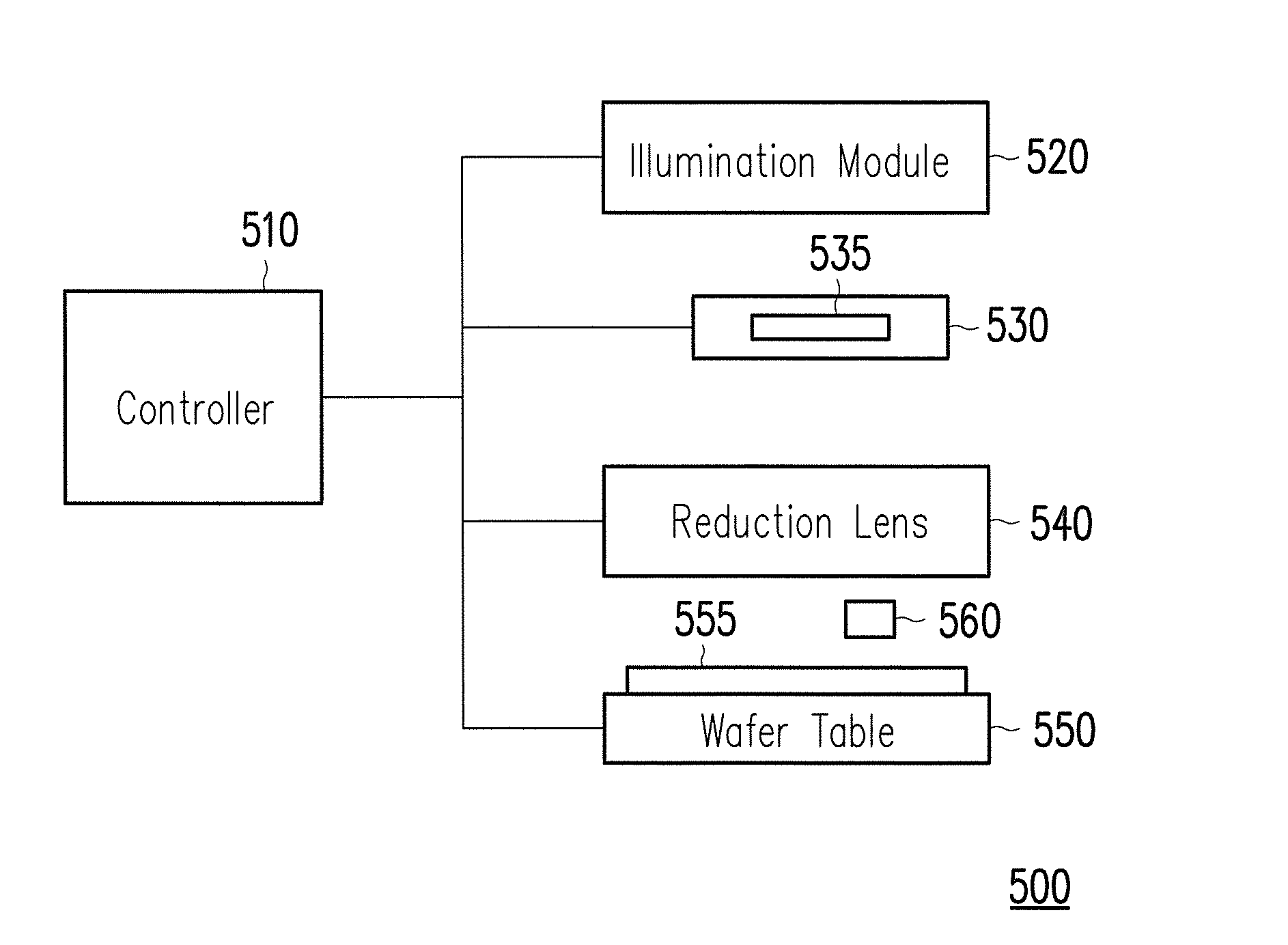
[0022]FIG. 5 is a schematic diagram showing a scanner 500 for performing an exposure process according to an embodiment of the present invention. The scanner 500 includes a controller 510, an illumination module 520, a photomask holder 530, a reduction lens 540, a wafer table 550, and an alignment apparatus 560. The photomask holder 530 is configured to hold a photomask 535. The wafer table 550 includes at least one chuck hole to attach a wafer 555 to the wafer table 550 by vacuum chucking. The alignment apparatus 560 serves as a reference point for the alignment of the wafer 555. The controller 510 is coupled to the illumination module 520, the photomask holder 530, the reduction lens 540, and the wafer table...


PUM


Abstract

A scanner and a method for performing an exposure process through a photomask on a wafer are provided. The exposure process includes an alignment step and an exposure step. The method includes the steps of moving a wafer table to align the wafer with an alignment apparatus, wherein the wafer table includes at least one chuck hole to attach the wafer to the wafer table by vacuum chucking, detecting an actual position of each of a plurality of alignment marks on the wafer, calculating an index value based on a difference between a predicted position and the actual position of each alignment mark, adjusting a vacuum pressure of the at least one chuck hole in the alignment step when the index value is larger than a first threshold value, and finishing the exposure process when the index value is smaller than or equal to the first threshold value.

Description

BACKGROUND OF THE INVENTION[0001]1. Field of the Invention[0002]The present invention relates to an exposure process. More particularly, the present invention relates to a scanner and a method for performing an exposure process through a photomask on a wafer.[0003]2. Description of the Related Art[0004]Exposure is an essential part of photolithography process for manufacturing semiconductor devices. An exposure process includes an alignment step and an exposure step. In the alignment step, the wafer is aligned with an alignment apparatus of the scanner. When there is a previous layer of image already formed on the wafer, the previous layer has to be very precisely aligned with the alignment apparatus to ensure that the current layer of image will be formed on the wafer at the desired position. In the overlay measurement step after the photolithography process, the overlay mark location between currently layer and previous layer is measured for checking the alignment performance of t...

Claims


Application Information

Patent Timeline
IPC IPC(8): G03F7/20
CPCG03F7/70775G03F7/70708G03F7/707G03F7/70633G03F7/70783G03F9/7011H01L21/682
Inventor YANG, CHIN-CHENGHUANG, CHI-HAO
Owner MACRONIX INT CO LTD
Why Eureka
Try Eureka